Results 1 to 6 of 6

Thread: Driver input impedance help

  1. #1
    Join Date
    Mar 2009
    Location
    New Orleans, LA USA
    Posts
    402

    Default Driver input impedance help

    I just finished installing 445 into my projector but ran into a problem I hadn't thought about.


    When I run just my LW 473 everything is fine.
    When I run just my Die4Drive 445 everything is fine.
    BUT when I tun them with the MOD lines tied together i can tell that there is a significant power drop on my LW 473.

    Buffo had commented in another thread of mine that "the input impedance on that driver is a little low, and that's pulling down the voltage on the modulation input to both drivers."

    and then he posted this circuit

    http://www.photonlexicon.com/gallery...uffer.bmp.html


    Basically this is where I get stuck. I have no idea what that schematic says or waht is does but I know it will solve my problem.\

    I'm looking for someone who would be interested in building this circuit for me. I can pay whatever you think would be fair.
    the only ting I would like to see different from that schematic would be the board should be 2 channel (445 and 660) and needs to run off the +9v supply I have (NOT +-9v)

    Please, anyone interested PM me or respond here.

    Thanks for taking the time to read all this
    -Brooks
    10W RGB
    2x 5W RGB
    2x 3W RGB
    2x 1W Green
    ---------------------------------
    QM.NET, 2x FB3, LivePro, Beyond, APC40,

    kgblasers.com

  2. #2
    Join Date
    Dec 2007
    Location
    Nottingham, UK
    Posts
    2,845

    Default

    Brooks,
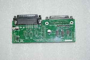
    Not meaning to spam, but MatILDA boards should be suitable. It is a larger version of that circuit with more features (ESD line protection, over voltage on signal lines etc.)

    Just to note: You would need 2 sets of Buffo's pictured circuit (one for '+', one for '-') if differential signals are used.

    You could run all the signal lines through MatILDA except the 445nm line. Then tie them together.
    Or rewire onto any of the ±X, ±Y, ±Intensity, ±R, ±G, ±B channels to buffer the lines needed.

    As for power supplies...
    The op-amps NEED two rails. '+' and '-'
    MatILDA incorporates a rectifier; so you only need to supply a single 12V AC supply, and the ± rails are internally generated.


    MatILDA boards are in stock, and ready to ship next day

    Best Regards,
    Dan
    - There is no such word as "can't" -
    - 60% of the time it works every time -

  3. #3
    Join Date
    Mar 2009
    Location
    New Orleans, LA USA
    Posts
    402

    Default

    matILDA looks great, and would definitely work, but its allot bigger than what Im looking for.
    10W RGB
    2x 5W RGB
    2x 3W RGB
    2x 1W Green
    ---------------------------------
    QM.NET, 2x FB3, LivePro, Beyond, APC40,

    kgblasers.com

  4. #4
    Join Date
    Jan 2007
    Location
    Sheepsville, Wales, UK
    Posts
    3,406

    Default

    Quote Originally Posted by KGB View Post

    Basically this is where I get stuck. I have no idea what that schematic says or waht is does but I know it will solve my problem.\
    You need a ready made solution if you dont understand the circuit
    Quote Originally Posted by KGB View Post
    I'm looking for someone who would be interested in building this circuit for me. I can pay whatever you think would be fair.
    There is a ready made solution with a fair price as Dan Suggested
    Quote Originally Posted by KGB View Post
    the only ting I would like to see different from that schematic would be the board should be 2 channel (445 and 660) and needs to run off the +9v supply I have (NOT +-9v)
    The op amp circuit will work from a single 9v supply but this will not provide enough swing +/- 4.5v so you wouldn't be able to run it from 9V without a dc-dc convertor but if you dont understand the circuit you prob wont understand that.
    Quote Originally Posted by KGB View Post
    Please, anyone interested PM me or respond here.
    I think you will find Dan did just that!

    Quote Originally Posted by KGB View Post
    matILDA looks great, and would definitely work, but its allot bigger than what Im looking for.
    Its not exactly a giant! and is that way as it buffer 6 channels - complete solution on a plate for you that as you say will definetly - we cant say any more than that.

    Rob
    If you need to ask the question 'whats so good about a laser' - you won't understand the answer.
    -----------------------------------------------------------------------------------------------
    Laserists do it by the nanometre.

    Stanwax Laser is a Corporate Member of Ilda

    Stanwax Laser main distributor of First Contact in UK - like us on Facebook http://www.facebook.com/FirstContactPolymerCleaner
    www.photoniccleaning.co.uk

  5. #5
    Join Date
    Aug 2010
    Location
    London or Spain depending on the weather
    Posts
    1,390

    Default

    Quote Originally Posted by KGB View Post
    matILDA looks great, and would definitely work, but its allot bigger than what Im looking for.
    Hi KGB. It occurs to me that if you only have a +9vdc supply you could just use opto-couplers which might be easier for you to understand.

    The led side of an opto-coupler is just a LED which needs very little current meaning that you can create a high impedance input just by putting in a series resistor of about 5k.
    You can't see the led cos it's inside the plastic. The photo transistor (also inside) does see the led however and will conduct but only in one direction and proportionately to the brightness of the led.

    As far as wiring the input is concerned you only have two possibilities.
    One way works but swapping the signal polarity won't work but won't hurt anything.
    The output is slightly more complicated but still fairly safe and easy.

    Get a few 1/4 watt (normal size) resistors with roughly a five to four relationship say 3 x 500ohms and 3 x 400 ohms .

    Take one of each and bridge them in series across you 9vdc supply with the smaller value to pos and larger to neg. This should give a 5vdc center point.
    From this point you connect to the +mod input of the laser driver and the negative side of the mod input you connect through the photo transistor side of the opto-coupler to the neg side of the PSU.
    Once again if you get it wrong it will do nothing but if you get it right it will work and hopefully the laser will come on to max power when the led side of the opto-coupler is fully lit.

    If the laser still does not come fully on just add another 400 and 500ohm resistor in parallel with the first ones.
    Your center point will still be 5vdc but can now supply double the current to the laser.
    As you add more resistors in parallel you increase the available current to drive the mod input of the laser driver (you also create more heat in the projector but only minimally.
    You can use an IC base for your connection soldering and on most opto-couplers one side is input and the other output so you can leave it free floating on the leads and (once the IC is plugged in and working) you just need to use some heatshrink to insulate it from an nearby metal.

    You only need to do this with the driver which has the low input impedance. The other one can just be in parallel from the mod input line before the 5k resistor that goes to the led.
    You can however (if you want to) use the same system for the other laser driver and they will then be fully opto-isolated from the control signal.

    I hope this is understandable for you and helps to enable you to DIY.

    Cheers

  6. #6
    Join Date
    Mar 2009
    Location
    New Orleans, LA USA
    Posts
    402

    Default

    Thanks for everyone's help. I ended up getting matILDA, a little more complex than I originally was planning on but will definitely fix my issue, and give me room to upgrade

    -Brooks

    10W RGB
    2x 5W RGB
    2x 3W RGB
    2x 1W Green
    ---------------------------------
    QM.NET, 2x FB3, LivePro, Beyond, APC40,

    kgblasers.com

Posting Permissions

  • You may not post new threads
  • You may not post replies
  • You may not post attachments
  • You may not edit your posts
  •