Page 1 of 2 12 LastLast
Results 1 to 10 of 13

Thread: Another one for electronics geeks

  1. #1
    Bradfo69's Avatar
    Bradfo69 is offline Pending BST Forum Purchases: $47,127,283.53
    Join Date
    Jul 2010
    Location
    Wilmington, DE
    Posts
    6,206

    Default Another one for electronics geeks

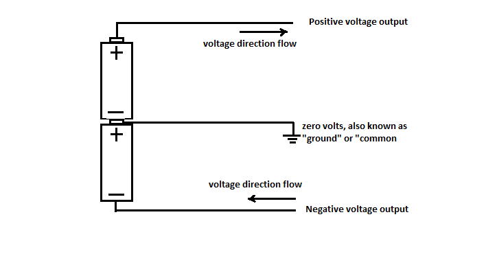
    Ok, just another one to throw out there since I as always, I admit to being ignorant of electronics. When the term 24v positive versus 24v negative is used. What the heck is meant by negative? I understand applying 24 volts to something. Whether it's taping together a bunch of batteries or, turning the dial on a benchtop power supply up to 24 volts. But, how do you get "negative" voltage?? How do you even meter that? The needle on a VU meter stops at zero. Would you get "UN shocked" if you touched it?? I could probably google it but, answers here are often better explained.

    Thanks!

    Signed...
    "Confused in Delaware"

  2. #2
    Join Date
    Jan 2007
    Location
    Florida
    Posts
    4,382

    Default

    The electrons are flowing in the opposite direction in reference to the ground, or the common of the circuit/wire (compared to the positive.) Negative electron flow is still electricity flowing, it's just travelling in the opposite direction than the positive electron flow. (hope this helped :]
    Last edited by steve-o; 04-14-2012 at 10:49. Reason: spelling

  3. #3
    Join Date
    Feb 2010
    Location
    Melbourne, Australia
    Posts
    1,106

    Default

    Assuming you have a power supply with positive, negative and ground terminals...

    On most modern meters, if you connect the black probe to ground terminsl and use the red probe on the positive terminal, you should see a positive number on the meter. Now connect the red probe to the negative terminal keeping the black probe connected to ground, you should see a minus sign in the meter readout.

    If you have a 9v battery, you can get the same result by measuring the voltage in reverse - black to positive, red to negative.

  4. #4
    Join Date
    Feb 2007
    Location
    Delaware USA
    Posts
    794

    Default

    Hey Brad,
    If you have two of the same voltage power supplies, connect both negative (black) leads together which form your common then, connect one of the positive (red) leads to your + input and the other positive (red) lead to - input of your driver board. That way, the + voltages are flowing in opposite directions from the common.

    Mark

  5. #5
    Join Date
    Feb 2010
    Location
    Melbourne, Australia
    Posts
    1,106

    Default

    Quote Originally Posted by ImageLight View Post
    Hey Brad,
    If you have two of the same voltage power supplies, connect both negative (black) leads together which form your common then, connect one of the positive (red) leads to your + input and the other positive (red) lead to - input of your driver board. That way, the + voltages are flowing in opposite directions from the common.

    Mark
    Um, I think you mean join one power supply's positive to the other's negative (not the 2 negatives together) and call this ground. Then connect the available positive to the positive input on your galvo amps and the available negative to the negative input on your galvo amps, and the new ground you created to the ground input of your galvo amps. Doing what you suggested would feed +24v into both the positive and negative inputs of the galvo amps.

  6. #6
    Join Date
    Feb 2010
    Location
    Melbourne, Australia
    Posts
    1,106

    Default

    My projector wiring diagram below shows how I've done this...

    Attachment 15529

  7. #7
    Bradfo69's Avatar
    Bradfo69 is offline Pending BST Forum Purchases: $47,127,283.53
    Join Date
    Jul 2010
    Location
    Wilmington, DE
    Posts
    6,206

    Default

    Thanks guys. I'll read this more slowly and digest it when I'm not so tired. I posted this morning just before leaving for work and am now just coming home from work.

  8. #8
    Join Date
    Apr 2006
    Location
    Miami, FL
    Posts
    3,590

    Default

    lets take a really basic power supply and look at whats happening


    ok this is a basic linear regulated +/-12VDC supply... you have three "connections" or outputs... at the bottom right, you have your +12VDC and -12VDC along with the grounds the 4 sequentially smaller lines pointing down are ground

    voltage is all about difference, so ground is generally accepted to be 0VDC, so if you were to measure from 0 to the +12VDC terminal you get 12VDC, from 0VDC to the -12VDC terminal, -12VDC... if you measured across both, so from the -12VDC to +12VDC terminals you would get 24VDC, or the difference between whatever the first and second one is...

  9. #9
    Join Date
    Jan 2007
    Location
    Florida
    Posts
    4,382

    Default

    Or, to further simplify, for those not familiar with schematics, we can look at a simple dual battery positive and negative voltage "power supply" :


    (I'm not getting into hole or electron flow theory, as far as the direction that the arrows are pointing .. )
    Last edited by steve-o; 04-14-2012 at 10:38.

  10. #10
    Join Date
    Jul 2008
    Location
    My momentum is too precisely determined :S
    Posts
    1,777

    Default

    Voltage doesn't flow, but current does! ;D
    Also electrons flow from negative to positive, but current is defined to flow from positive to negative. Just so you know.

Posting Permissions

  • You may not post new threads
  • You may not post replies
  • You may not post attachments
  • You may not edit your posts
  •