Can I use the monitor, monitor1 pads to adjust the current ?Originally Posted by megaton


 Senior Member
Can I use the monitor, monitor1 pads to adjust the current ?
Senior Member
Yes but with .33 resistor is no direct reading like with the 1 Ohm.
With 1 Ohm you read 1mV for 1mA. But for .33 the mV you read you have to multiplied for 3.0303 times to get your real mA.
Ohms Law
Cheers,
Eduardo
Senior Member
Yeah so I actually measure voltage and convert it to amps. I thought I could use the amperometer in series to get the current instantly ?
Senior Member
Yes you can do that but I go with the Volts reading because is more easy in parallel and
more accurate. Amperometers put some load in the circuit and for mA reading is not good.
Senior Member
Do you use batteries or something else( maybe an adc/dv converter ) ?suggest you go for 12 Volts PSU and .33 Ohms 1 Watt and a heat sink for your transistor.
Senior Member
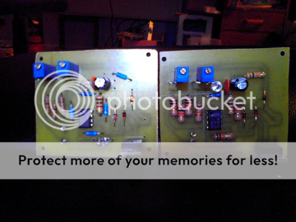
Okay so i etched and made 2 of these drivers.
It was my first time making a driver and etching my own board using the toner transfer system.
All in all, it went great had to touch it up with a sharpie and it was perfect.
Okay so my question is i see the place for the modulation line but thats only the positive if i am using my sound card dac do i just ground the negative wire to the negative on the driver board?
I am almost 100% sure that's what i am should to do but i just don't want to ruin anything before i start.
Also i only had a 1ohm Smd resistor so it there in the picture but on the reverse side.
And on my other board i am going to be using a 445nm laser at high powers so i am using a 100uf 35v cap and i have 3 1ohm resistors in parallel for about 0.33 ohm at around 1W.
just for shits and giggles i have a red led for the red driver and a blue for the blue driver.
I did not have the same pots so i decided to mount mine upright.
They are glued on the bottom so there is no stress on the pins.
Here are some pictures of my 2 new boards.
If you like how my boards look i can etch some for you.
I hear alot of people have problems etching for some reason.
Just shoot me a pm.
I know this sounds weird as this goes against the whole idea of this driver, but i wish there was a schematic for this that would be smd for all parts but the transistor.
That way it would be nice and small. i find smd parts easy to work with. i just put a tiny dap of glue then place them and a little bit of heat melts the solder under them.
Last edited by kiyoukan; 10-12-2010 at 23:44.
Senior Member
Kiyoukan, did you test the drivers whether they work or not ?
Senior Member
It seems to work...
I have one running at 12v and its outputting 1.3A and another running off 5.5v and it outputting 400ma.
But i cant seem to get the signal wire to work. i put it to 5v high and nothing happens.
I am using a different transistor.
MJE3055Tjp its rated to 4a the only difference is it has to be mounted backwards for the pins to line up.
but it should be working wish someone might be able to get on and answer a few questions tho.
Senior Member
Guys, did I place the components the correct way ? please tell me if I have done something wrong..

Senior Member
Hi
1-The red Led, I think is just for 20mA and there were suppose to be the Led Laser.
2- The 1 ohm resistor is in the green led (try that with 470 0hms).
3- The shunt resistor looks like a 10 ohms instead of 1.
All other parts looks fine.
Try to adjust first with a dummy load (4 diodes in series 1n4001 for red or 6 for blue)
I put 1N4007 and also work.
And put a voltmeter in the Monitor to adjust. (for 1mV = 1mA)for the 1 ohm shunt.
And the presets for me work Idle for Max current and Main for threshold or idle.
But I adjust it just perfect and work fine at the end.
I hope this help
Cheers,
Eduardo
BTW nice cutting.....
Last edited by megaton; 10-13-2010 at 12:58.

 Posting Permissions

 Reply With Quote