Page 5 of 8 FirstFirst 12345678 LastLast
Results 41 to 50 of 77

Thread: Need some help! My first RGB projector project (expecting approx. 2W system)

  1. #41
    Join Date
    Feb 2010
    Location
    Melbourne, Australia
    Posts
    1,106

    Default Video

    Here's a short video...


    I am working on it in a spare room perfect for this sort of thing. So no, my lounge doesn't look like that

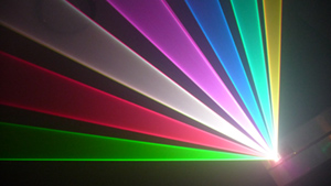
    As you can see from the first clip, the unwanted transmission (and reflection) through the laser-wave dichros looks high. I'm still keen to have measurements taken to establish the loss. I have tried a number of different angles and flipping the filters over 180 degrees without any noticeable improvement. In the second clip, I have masked these two extra beams.

    I'm otherwise happy with these initial results and looking forward to completing the construction in the next week or so in preparation for it's first night out April 17th!
    Last edited by taggalucci; 04-01-2010 at 16:41.

  2. #42
    Join Date
    Jan 2006
    Location
    Charleston, SC
    Posts
    2,147,489,459

    Smile

    Wow! It's coming together rather quickly now... Already got it scanning I see. Very nice.

    Keep up the good work!

    Adam

  3. #43
    Join Date
    Aug 2007
    Location
    Under a rock in Cambridge UK
    Posts
    1,353

    Default

    I really like this AC distribution:

    Click image for larger version. 

Name:	IMG_0131_..jpg 
Views:	84 
Size:	53.2 KB 
ID:	15901

    Is it something you made or did you buy it? I would be very interested in getting hold of one...

    Mark

  4. #44
    Join Date
    Feb 2010
    Location
    NJ
    Posts
    270

    Default

    Mark,

    Check out McCarrot's post here for the board he is designing:

    http://www.photonlexicon.com/forums/...102#post142102

  5. #45
    Join Date
    Dec 2008
    Location
    Southport, UK
    Posts
    2,746

    Default

    Yes, McCarrot's board sounds like the ultimate laser builder's must have: Interlock circuit, AC distrubtion and switching, ILDA buffer and connector and all on one board, bring it on

    After spending every night this week scheming out and soldering up 2 interlock and AC distro boards I would gladly pay for some next time, my eyes aint what they used to be and I still need to build some buffers for my Laserwave modules
    http://img62.imageshack.us/img62/3985/laser.gif

    Doc's website

    The Health and Safety Act 1971

    Recklessly interfering with Darwin’s natural selection process, thereby extending the life cycle of dim-witted ignorami; thus perpetuating and magnifying the danger to us all, by enabling them to breed and walk amongst us, our children and loved ones.


  6. #46
    Join Date
    Feb 2010
    Location
    Melbourne, Australia
    Posts
    1,106

    Default

    Quote Originally Posted by Insanity View Post

    Is it something you made or did you buy it? I would be very interested in getting hold of one...

    Mark
    Hi Mark,

    Yeah, this was something I made from various components bought at a local electronics store (equivalent to Maplin).

    This provides somewhere to wire each separate AC-requiring component (without sharing terminals) and somewhere to mount the fuse (for easy access). I later added a switch to isolate the scanner amps for when I'm maintaining or aligning and don't need them powered.

    It's not that tidy, but very robust. Glad you like it

  7. #47
    Join Date
    Feb 2010
    Location
    Melbourne, Australia
    Posts
    1,106

    Default

    Quote Originally Posted by dave View Post
    They were the new laser-wave dichros, so the losses should be minimal.

    Maybe I can drop past sometime to meter your lasers and check the losses of your dichros with the fieldmaxII or gentec meters we have here..?
    Thanks to Dave and Adrian for popping round this arvo with their power meters.

    I believe the loss off the first dichro was about 110mW of red, so from a 900mW laser that was quite significant. Dave's taking this up with Laser-Wave and I look forward to hearing more.

    Thanks again guys, and good to meet you both

  8. #48
    Join Date
    Feb 2010
    Location
    Melbourne, Australia
    Posts
    1,106

    Default Building the housing...

    Hi all,

    Here's some pictures of the housing a friend of mine had milled from drawings I supplied...

    5 of the plates attached to the chassis frame, with lots of apertures for fans and vents...
    Click image for larger version. 

Name:	IMG_0195..jpg 
Views:	39 
Size:	38.8 KB 
ID:	16087

    View of the back with all the apertures for switches, connections etc...
    Click image for larger version. 

Name:	IMG_0193..jpg 
Views:	25 
Size:	34.8 KB 
ID:	16088

    View of the front...
    Click image for larger version. 

Name:	IMG_0194..jpg 
Views:	20 
Size:	33.1 KB 
ID:	16089

    I have now sent these off to be coated. I'm looking forward to seeing the finished product!

  9. #49
    Join Date
    Jan 2006
    Location
    Charleston, SC
    Posts
    2,147,489,459

    Thumbs up

    Looking good! Wow - Lots of airflow through that case...

    Adam

  10. #50
    Join Date
    Dec 2008
    Location
    veenwouden
    Posts
    2,580

    Default

    keep your optics out of the airflow if you want to keep your optics clean

Posting Permissions

  • You may not post new threads
  • You may not post replies
  • You may not post attachments
  • You may not edit your posts
  •