Page 2 of 2 FirstFirst 12
Results 11 to 14 of 14

Thread: Can someone help me tune my green laser?

  1. #11
    Join Date
    Nov 2007
    Location
    Cairns, Australia
    Posts
    1,896

    Default

    Not exactly sure how I would check if the power supply is lagging under the load, since it's part of that driver.

    Would a graph of the laser output while I adjust both of the pots help figure out what each pot is for?

    I'm gonna have a crack at finding the pinout of the head. I know the diode voltage will be around 2V or so, the fan voltage will be >5V, then that just leaves the TEC and thermistor.

    OK, pins 1 and 2 seem to be the diode.
    Last edited by Things; 03-06-2010 at 02:56.

  2. #12
    Join Date
    Dec 2008
    Location
    Southport, UK
    Posts
    2,746

    Default

    Quote Originally Posted by Things View Post
    Not exactly sure how I would check if the power supply is lagging under the load, since it's part of that driver.

    Would a graph of the laser output while I adjust both of the pots help figure out what each pot is for?
    Bummer, no, you'll need to scope it.
    http://img62.imageshack.us/img62/3985/laser.gif

    Doc's website

    The Health and Safety Act 1971

    Recklessly interfering with Darwin’s natural selection process, thereby extending the life cycle of dim-witted ignorami; thus perpetuating and magnifying the danger to us all, by enabling them to breed and walk amongst us, our children and loved ones.


  3. #13
    Join Date
    Nov 2007
    Location
    Cairns, Australia
    Posts
    1,896

    Default

    Closeup of the output:


    I get 1.8V between pins 1 and 2, which is obviously the diode. I seem to get -3V or so between pin 3 and 2 though. Let me do some more measuring.
    -0.13V between 3 and 4 ...
    -5.48 between 6 and 8 (7 not connected)...
    -5.3V between 5 and 4 ...

    I'm probably metering these backwards. Oh well lol

    Hmm, adjusting the pot on the right seems to change the voltage between pins 3 and 4. Maybe this is my TEC?

    OK so, I think the pot on the right may be the TEC. Why: Adjusting this adjusted the stability and output drastically. 2, one of the pins from that pot run to the TEC output.

    The pot above the diode current I'm still not sure on. I tried turning it both ways with the modulation on 0V, and the diode didnt light or anything, so I dont think it's diode bias.

    This driver may be made for multiple laser heads, thus the XS5 output header, which seems to only carry the diode and TEC power.

    Any other idea's for what it could be?

    Interestingly, adjusting the pot above the diode current pot also adjusts the output power.If I turn the pot above the diode current all the way clockwise, the output drops to nothing (Like diode current). This happens pretty much instantly as well, so seems like it's not temperature controlling anything.

    If I set that pot to where it is dull, the pot I thought was diode current allows me to adjust the brightness between that point and nothing. Interesting ...
    Last edited by Things; 03-06-2010 at 03:34.

  4. #14
    Join Date
    Nov 2007
    Location
    Cairns, Australia
    Posts
    1,896

    Default

    OK, I have it to a point where it reliably starts up to around 210mW and sits there nice and stable. It does still flicker a tiny bit if I switch from say some graphics, to something simple like a circle, but only for the first few seconds, then it settles down a bit.

    I can't tell for sure until I reconnect all my galvo's and have a look at the pattern, but it seems OK for now

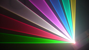
    Threw a lense on the front for a bit of fun. The power output is quite amazing now! Plastic lense too.

    This is normal paper, no starter mark:

    Last edited by Things; 03-06-2010 at 05:27.

Posting Permissions

  • You may not post new threads
  • You may not post replies
  • You may not post attachments
  • You may not edit your posts
  •