i need to wire some die4laser drivers together.
i dont want to go from one to the other as one will ending up with a number of amps going through its contact pad.
anyone know of any decent splitters that i could use?

 Senior Member
i need to wire some die4laser drivers together.
i dont want to go from one to the other as one will ending up with a number of amps going through its contact pad.
anyone know of any decent splitters that i could use?
Eat Sleep Lase Repeat
Senior Member
Something like this? ...hold on.
New link
"C060 6 Way DC power splitter * Conductor: BC
* Jacket: PVC
* Plug:5.5mm*2.5mm,5.5mm*2.1mm or 3.5mm*1.35,Nickel Plating
* Min Order: 500PCS <<< EWWW!
* Lead time: We can have the goods ready within 7-10 days usually.
* Sample is free. <<< I like that one.
* Small order and customized products accepted. <<< That one too."
Last edited by Occularis; 04-04-2010 at 11:07. Reason: Fixed dead link
Senior Member
If you're trying to get lots of current to a pump diode, you can try adding equal value resistors commoned at the diode end but each going to the driver board's output at the other. That driver controls current so the diode will see the sum of set currents, so long as that diode works. If it goes opencircuit I won't try to predict what happens. Might be safe, but I haven't explored the circuit recently so i don't know. (Been working on my own design recently..)
If this doesn't make sense, then you might need to rethink your context (and explain it here because I can only guess. But the only reason I can think of to combine driver outputs is to boost current to a single hungry diode. In which case there are neater and less costly ways than lots of complete driver boards.
If you're only after wiring power to them all you could use a ring-main wire, it's solid, carries a few tens of amps, the sheath is easy to strip and slide along it so you can solder little feed wires from it to each PCB, then slide back each bit of sheath to almost hide the joint.
Senior Member
not exactly what im after but ill bare it in mind thanksOriginally Posted by Occularis

Eat Sleep Lase Repeat
Senior Member
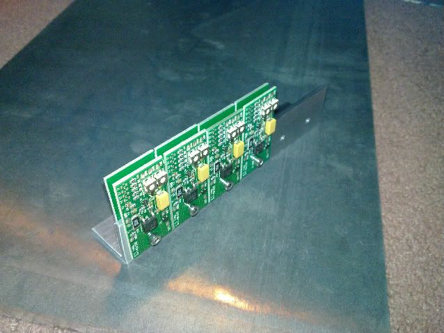
i just need to take a sinlge 5v out put and wire it to 12 drivers.
so am looking for sum kind of splitter. ring mains will probably be massive i was after sumthing smaller if possible. its only 5v
Eat Sleep Lase Repeat
Senior Member
Then use lighting wire, that's 1.5 mm square instead of the heavier 2.5 mm squared stuff for ring mains. Either way, it's easy, it stays put, it looks good. And it's amps not volts you need to worry about. Don't try to wire it to the boards, it's just a bussbar to run along the row of boards, then use finer stuff to go from bar to board.
Senior Member
Why not use a standard connecting block (the plastic ones also known as choc block)
Bring the power in from one end and then run little link wires between the terminals and then run your individual power runs from the points on the opposite side.
Senior Member

Doc's website
The Health and Safety Act 1971
Recklessly interfering with Darwins natural selection process, thereby extending the life cycle of dim-witted ignorami; thus perpetuating and magnifying the danger to us all, by enabling them to breed and walk amongst us, our children and loved ones.
Senior Member
Spot on.
Though I'd stagger the red/black nodes so there's less risk of a short between high-current bussbars. Good to see that someone fully gets it though. Bussbars nearly always look cool, and this is a dirt-cheap way to make nice ones. Might be best to avoid the bars running over the drivers though, unless space is tight and access to pots is still good.
Senior Member
how about use one or to tracks from a PCB stripboard to make a bus-bar? the stripboard could be fastened down securely then instead of having a row of floating wires by your drivers.
The tracks could be painted over/ concealed once soldered, to stop anything touching the tracks and blowing up your drivers/etc
p.s. please appreciate my masterpiece of paint-editing here!

 Posting Permissions

 Reply With Quote