Senior Member
Senior Member
Senior Member
order placed ! If this works out I can can my dpss and perm seal my projector.
Senior Member
Amazing modulation and beautiful color. You're going to like these diodes!Originally Posted by kecked

If you're the smartest person in the room, then you're in the wrong room.
Senior Member
How does the PLP520 look vs. the PL520? Obviously higher power, but spot size, shape, etc? I'd like to add non-DPSS green, and was planning to get a PL520 (since I don't need high power), but I'm thinking of "future-proofing" and get a higher power for the day that I decide I need to upgrade the projector.
Also, does anyone know anything about the projector power supplies? https://sites.google.com/site/dtrlpf...power-supplies Output voltage(s), current, etc?
Thanks,
DogP
Senior Member
My general rule with new tech is don't buy more than you need now. By the time you do need more, prices will have dropped and new models will be available.... Of course, its your money....
This space for rent.
Senior Member
I'm waiting for the new 1W 520 Nichia diodes to hit the $200 mark. Waiting .. waiting .. waiting .. all this waiting ..")
Last edited by steve-o; 01-12-2014 at 10:53.
Senior Member
Yep, I kinda agree with that, except the price difference is only $50. I could be wrong, but I think it'll be a while before I can get a 250mW 520nm for $50. If the PL520 (or PL515) was cheaper, my decision would be easy.
Heh, yep. Those look pretty sweet! That'd be REALLY overkill for me though.
So nobody has ordered a box full of power supplies yet?Heh, the "box" quantity kinda scares me away... I want one, maybe two of each. With unknown specs, I'm not sure I even want that.
DogP
Member
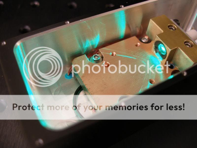
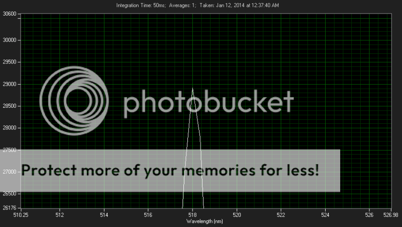
I did some temperature testing on the PLP520 diode over the weekend to see if it shifted in WL going up in current and at a couple of temps.
I only took one reading at 0C though. I dont see the WL shifting much more if i went to -10C.
I dint pay to much attention to power increase but i did notice around a 30mW increase going from 33C to 0C at 350mA.
I used my LDI-820 for the tec driver and my Opto-power Driver for the diode.
Here is the module setup i used insides right before i sealed the cover on:
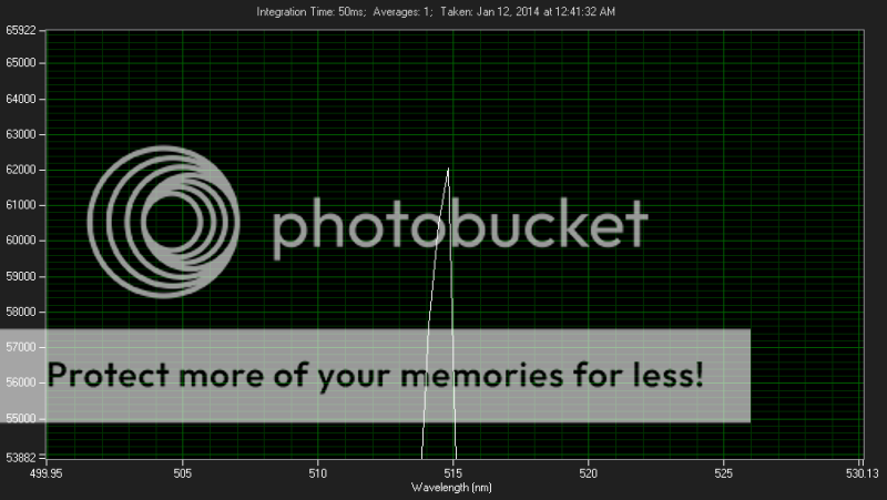
Around Threshold 110mA 5.4V at 25C:
Around Threshold 110mA 5.3V at 33C:
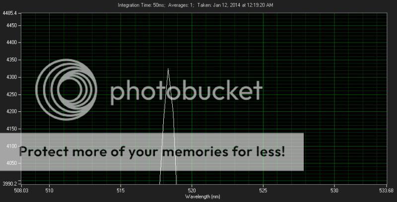
350mA 7V at 0C:
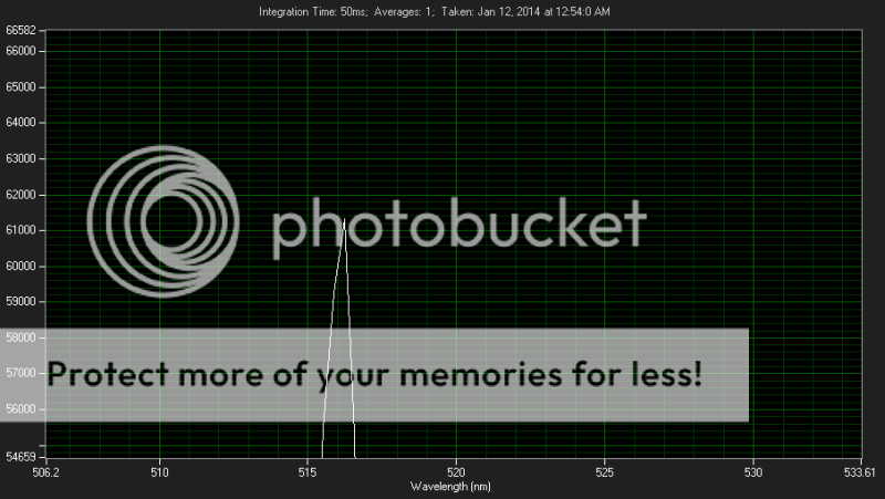
450mA 6.5V at 25C:
550mA 6.6V at 25C:
550mA 6.4V at 33C:
Within a common temp that one would run a diode at i dont see it shifting much.
The PL520 50mW IIRC was just like this. Maybe it shifted a little more but it wasn't much.
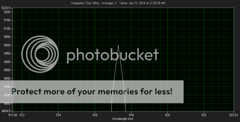
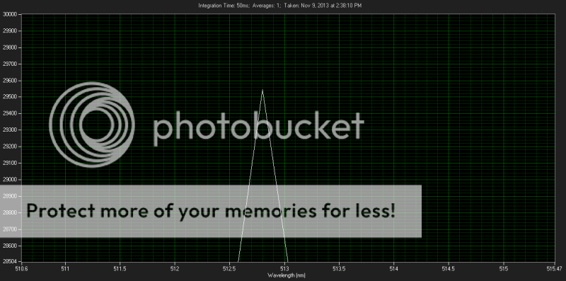
The PL520 i manged to get it to this at -31C 200mA at 80mW:
At 25C it was 517nm so thats ~.7nm per 10C
So ill have to test th PLP520 down to -31C and see what i get with the PLP520 but it looks like its going to be more or less around .3nm shift per 10C.
The voltage really shots up there on green diodes when you chill them.
If more of you are interested on the power increase i can do a test for you guys tomorrow at say -10C or -30C. I just need to set up the large TEC module i use or i would have done it now.
Iam hoping that if we chill them we can increase the current more to get more power out of them. Similar test i did on a 405nm diode it would top out at ~1W at 630mA at 25C but when chilled down to -10C it allowed me to go to 750mA and power increase to almost 1.2W before i stopped the test.
It would be interesting to see if we can get more out of them without causing damage or reducing life.
There is 4 bond wires. Just like the P7

Last edited by Lazeerer; 01-13-2014 at 01:14.
Senior Member
Thanks. Interesting results....
This space for rent.
Senior Member
I found a similarly small wavelength shift with the 445nm diodes. And, the increase in power output for a given current was also very similar to your results for the 405nm and the 520nm. They are all GaN diodes, so I guess this makes sense. The question regarding increasing maximum safe output will depend on whether it is the facet-face or the electrical system ie the bond wires that fail first. I think this will require a destructive test at some point, but one pre-distructive milestone might be to look at the efficiency slope. When the output vs current begins to diverge below the low power relationship this usually precedes destruction in the red diodes and at least suggests a point when higher current provides little additional benefit.

 Posting Permissions

 Reply With Quote