My 1w 637 kvant is definately not 2 diodes cross polarised. It's 2 rows of 3 points. There is no fringing.
I would say the 637 in the first pic is simply brighter and thus causes some blooming.

 Senior Member
My 1w 637 kvant is definately not 2 diodes cross polarised. It's 2 rows of 3 points. There is no fringing.
I would say the 637 in the first pic is simply brighter and thus causes some blooming.
Frikkin Lasers
http://www.frikkinlasers.co.uk
You are using Bonetti's defense against me, ah?
I thought it fitting, considering the rocky terrain.
Senior Member
There are a lot of mixed influences here ie camera with potential saturation/blooming,camera optics, the scanning process and then the diode(s) and diode optics. This makes the comparison way too open for debate.I would say the 637 in the first pic is simply brighter and thus causes some blooming.
I told Solarfire to wait on a Mitsu build because I am currently working on a filtered Mitsu module that may largely eliminate peripheral spill. I am very interested in how other red lasers compare on the contrast issue. We often here about divergence, but little is usually said about the quality of the spot.
Song,
Could you rather post comparative images of the static spots of these two lasers against a flat surface?
White-Light and norty,
Could either of you do the same with your Kvant?
Senior Member
Ok here is a suprise. Both pictures that i posted are 660nm.Its very hard to determine because the camera settings can fool you
637 is more orange then 660 but its hard to see.

Interested in 6-12W RGB projectors with low divergence? Contact me by PM!
Senior Member
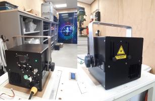
This is the red diode as a spot (to the eye its a perfect round spot of even colour) to the camera there are several different coloured zones:
The red splash above is the emissions LED's reflecting on the door, nothing to do with the laser beam!
This is the start shaped diode pattern, here the eye sees it better than the camera as the eye picks up visible feint tails that extend out further than the camera detects (btw the diodes power is almost down to the point of of them being extinguished to make this visible):
I've added some green arrows to make it a little more distinct although like I say in this case the eye picks it up better than the camera:

Senior Member
The top picture shows an inner spot and an annular zone surrounding this. What is the visible extent of the spot? I assume it's the outer diameter. And, are those two images of the same laser at different power levels? Oh, and thanks.
Senior Member
No top one is at full power. All the eye sees is a red dot of perfectly even colour of the darkest red visible.
The bottom one is of the diodes turned just about the point at which they lase. The higher you turn the power the less indistict the cross becomes to the point where you can only see a round spot.
One give away is red points that are modulated have a slight leading edge tail. Can't seem to remove this with blanking or other adjustments. Not noticible on beams but if you project beams in the form of a spot against a wall then the tail is there. Graphics have no visible problems (presumably because they're made up of lines not spots).
Re: The extent of the spot in the top pic. It's actually very tight. I'd guess from it's size the inner white area represents the spot. The rest is spectral reflection picked up by the camera. The laser is only about 5-6 feet away from the door so the spot is almost at aperture spec, I think Kvant quote 3.5mm 2.
Senior Member
Camera saturation will amplify the contrast of any artifacts present in the beam profile (especially red), the appearance to the eye directly will not be so pronounced like in a picture. I just built 2 quads with 71 mitsus and all of the diodes have these fringes more or less but not completely without. The diodes in White-lights Kvant are obviously single emitter diodes as the beam profile implies in post 24. In the first post, if you notice that the fringes are biggest in the top right hand corner of the scanned image, getting smaller to the bottom left. This is due to the fact that scanners have a max and a min clear aperture depending on the angles of the mirrors of the axis X and Y. Top right shows the aperture at its max (fringes are not truncated) and the bottom left shows the aperture at its min (fringes are truncated).
Member
**just notices that each post is numbered**
Needs moar photons
so much measurebation in this thread
Senior Member
Sorry, its all in the lockup and I'm not going to have the chance to get it in on the bench for a while.Could either of you do the same with your Kvant?
I can say that at close range, you see the individual dots of the diodes very clearly, and without fringing (the gaps between the points are very well defined, which means that the optics don't introduce unneccessary bloom - otherwise you'd see it there as well as in the farfield)
Once you get past 4ft or so the divergence means that the dots start to merge and overlap. Obviously (in theory) there will be less individual diodes overlapping on the perimeter, but you don't see the gradient, certainly not once the power gets up anyway and your eye starts to saturate. If you are shining it on any sort of surface, the diffuse reflection is by far the worst artifact, to the point that any gradient in the beam profile is a moot point.
Frikkin Lasers
http://www.frikkinlasers.co.uk
You are using Bonetti's defense against me, ah?
I thought it fitting, considering the rocky terrain.

 Posting Permissions

 Reply With Quote