thanks for the offer but i already have some being sent to me

 Senior Member
thanks for the offer but i already have some being sent to me
Eat Sleep Lase Repeat
Senior Member
ok a possible solution in an attempt to make a design to suit every projector.
a design where the fixing for the lens holder is below the output window, so all everyone would need to do would be to drill two holes in their casing nothing else. when the lens are not being used you could just put a screw in the two holes to stop dust getting into the projector.
the lens would be suspended in front of the out put window
the deisng includes, left and right movment up and down movement and angle adjustment of the actual lens. bit of a complex holder consisting of six parts but it will be nice and secure
what do people think?
Eat Sleep Lase Repeat
Senior Member
I think you're going to need to provide a drawing for us to see what the plan is Andy, or even a prototype!
Can the design accomodate a range of hole positions (widths specifically), for people with existing mounting points for shutters?so all everyone would need to do would be to drill two holes in their casing nothing else.
The word 'suspended' conjures up certain images in my mind (like a hammock!), images which are not usually compatible with the idea of something being supported from below (which the lower fixing point tends to suggest)the lens would be suspended in front of the out put window
Again, I think a picture is worth a thousand words.
Frikkin Lasers
http://www.frikkinlasers.co.uk
You are using Bonetti's defense against me, ah?
I thought it fitting, considering the rocky terrain.
Senior Member
this is the idea for the acutal lens holder part, so the lens cannot fall out full stop
theres two parts and front part and back part
Eat Sleep Lase Repeat
Senior Member
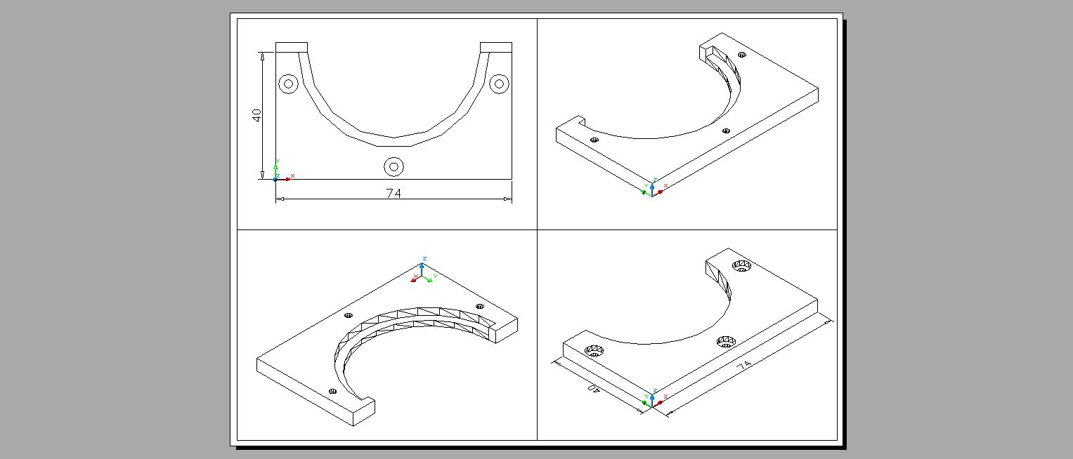
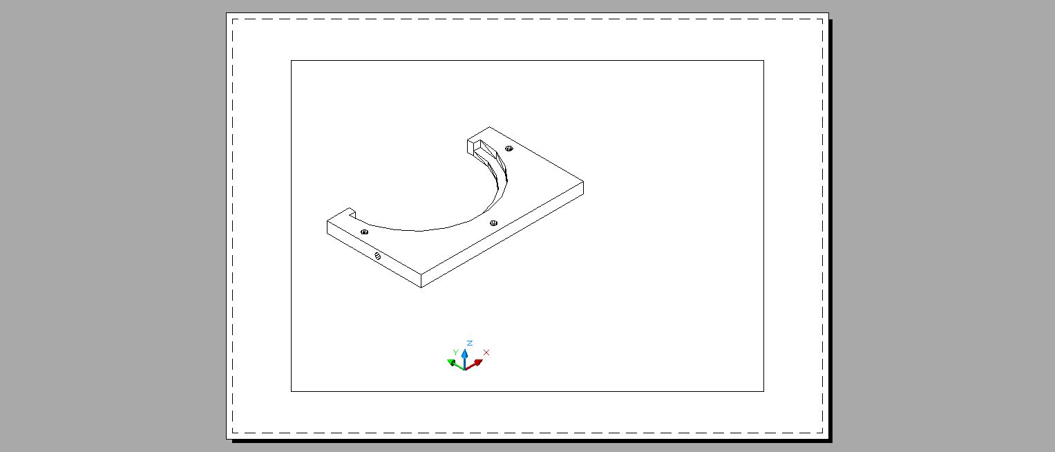
ok well here goes...
the first part is mounted/screwed to the projector case just before the output windows. the slot is 4.2mm wide to take two 4mm bolts and enables the whole mount to be moved left and right
second part is mount to the first part and has two 3.2mm slots to enable the lens to the moved up and down
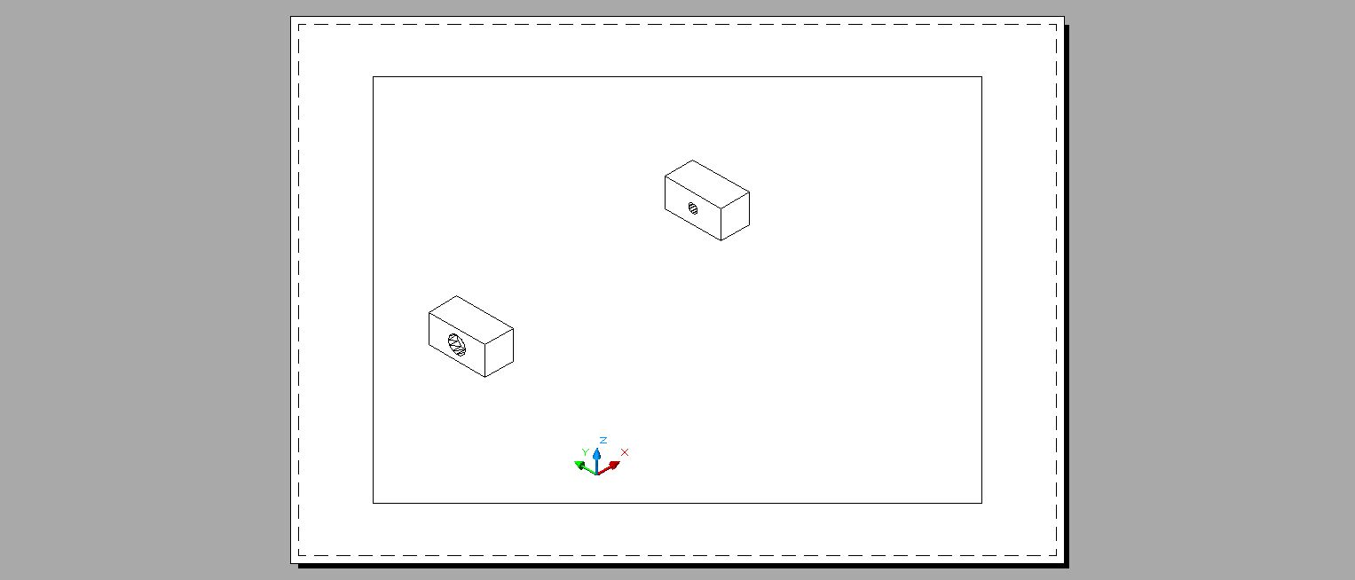
the third part(s) are two arms, that are mount to the second part and enable the lens to be tilted
the forth part is mounted to the two arms and is the back part of the lens holder
and the final part is mounted to the forth part to secure the lens in place
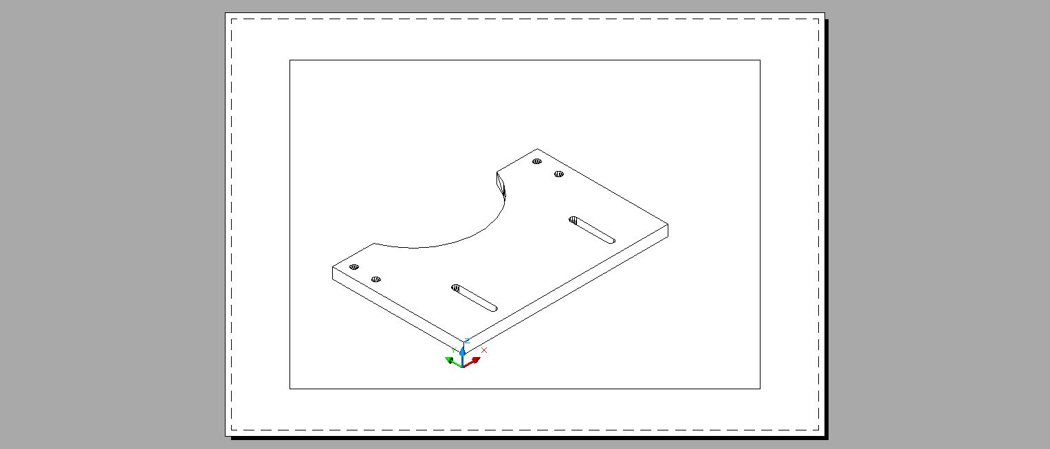
complete unit
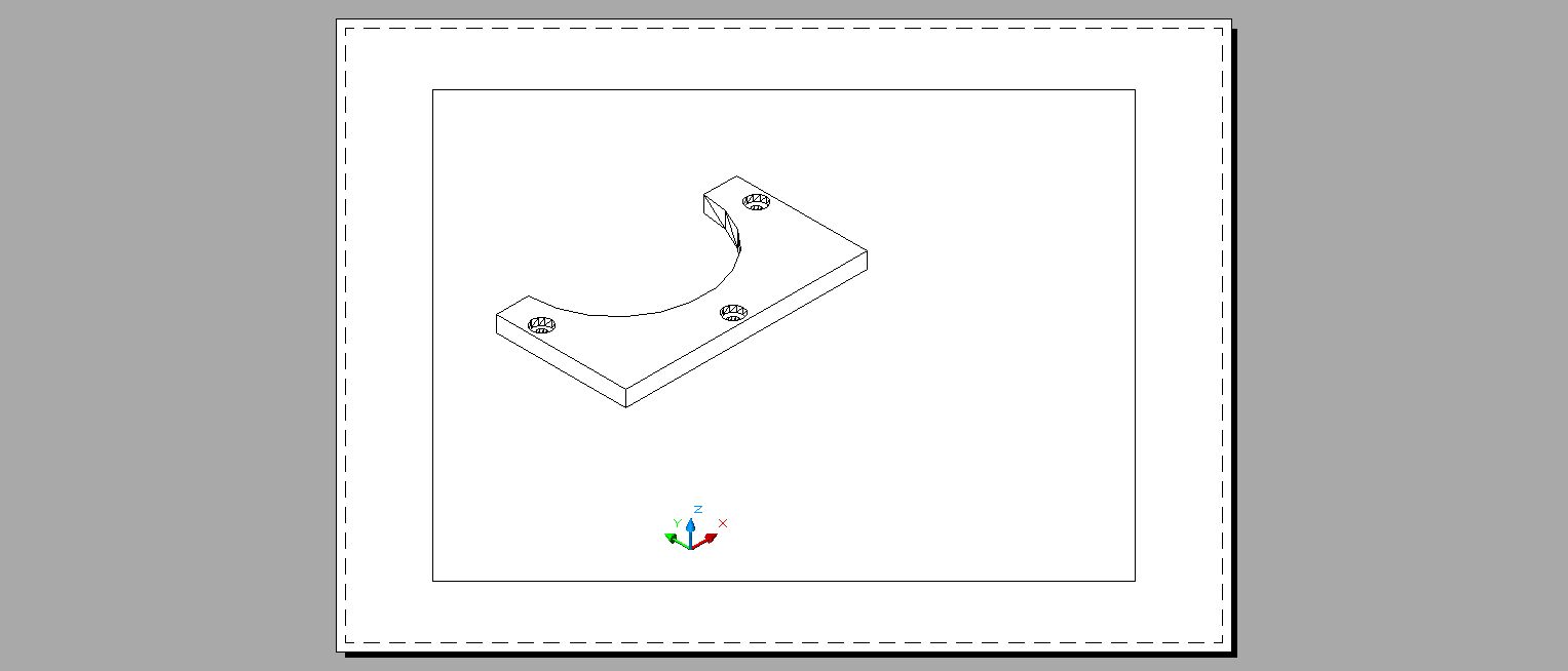
the reason i did it this way was to try and fit all projectors. the holder can be mounted below the projector window and as most projectors have some metal work sticking out around the aperture this hopefully deals with that by holding the lens away from the projector case.
the total thickness of the entire mount is 23mm
all comments welcome
Last edited by andy_con; 01-29-2013 at 15:14.
Eat Sleep Lase Repeat
I'm not quite seeing how the tilt action can come into play here. Unless the arms are taller (stick out further.) Or... the amount of tilt necessary for these lenses is a lot less than I realize. I know it's not much but, this illustration looks like there is hardly room for any tilt at all.
Other than that, looks pretty good to me.
Senior Member
Couple of quick observations.
I'll refer to the diagrams in the order you've posted them, A, B, C, etc
Part A I think needs to be as narrow vertically as possible, so it can fit on projectors that might not have completely flat fronts.
E.g. this one (which quite a few members have I believe)
http://www.goldenstarlaser.com/boxf-p-286.html
A narrow part A would probably just sneak in along the bottom there, with mounting either side of the bottom corners of the window.
I'd quite like to see what a mount was like where the lens fixed directly to part B (i.e. without the tilt part) This might also offer the possibility of mounting the lens in front of part B (for those with sticky outy apertures) or behind (for those with flush/recessed apertures)
The tilt adjustment could maybe be handled by shims in the mounting slot.
Once the lens is in place, I doubt many people will want to swap them out, they'll either be on or off. I thought initially that I'd be swapping all the time for the most appropriate for the venue, but even the -6 was only just in MPE at 15m with 800mW of 532, so I couldn't see the point in swapping for lower powr for slightly bigger venues.
I make that 3 parts then, the horizontal plate for the projector, the main plate, and the clamping plate.
Can the horizontal slot in the part A be machined to accept a countersunk screw? I can see the part B may need to be slid down over the top of the slot in some cases.
Frikkin Lasers
http://www.frikkinlasers.co.uk
You are using Bonetti's defense against me, ah?
I thought it fitting, considering the rocky terrain.
Senior Member
Seems like a set of rare-earth magnets would provide maximum flexibility and quick installation. Add some friction tape or a mating pair of magnets on the inside for need-a-screwdriver-to-pry-them-off fixation.
Senior Member
Hi guys,
Looks like you're doing a good job Andy
one idea I had to help reduce the machining operations and complexity it to make the two
Lens holding parts out of plastic. If it was only a few sets getting made, you could get them 3D printed by http://www.shapeways.com/ it cost around $1.40 per cubic cm. This would save you having to machine the round section with a rotary table if you are manual machining it or having to CNC interpolate it. Also you could take advantage of the flex in the plastic so the lens "snaps in" to the holding piece so it can be 1 part instead of two.
If you can reduce the volume of plastic you use by thinning out the holder to 5mm thick with webs and bosses where the strength is needed, it would probably be cheap enough to make a seperate lense holder for each lense.
Good work mate, let me know if you need any help.
Kit
Senior Member
Hi Tribble, that s a great idea! Maybe you have three magnets. 1 to the left, 1 to the right and one at the bottom. You could mount 3 grub screws next to them so you can use them as screw jacks to adjust the tilt, up down left and right.Originally Posted by tribble

Last edited by kitatit; 01-29-2013 at 18:36. Reason: Sausage fingers on iPhone

 Posting Permissions

 Reply With Quote
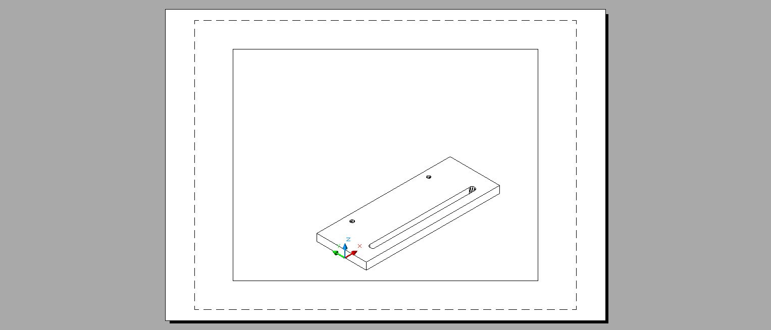

 Bradfo69