Page 8 of 12 FirstFirst ... 456789101112 LastLast
Results 71 to 80 of 114

Thread: Safetyscan lens holder, anyone developed one yet?

  1. #71
    Join Date
    Feb 2008
    Location
    East Sussex, England
    Posts
    5,248

    Default

    BTW, when I said threaded bar, I meant plain round bar, with an internal thread.
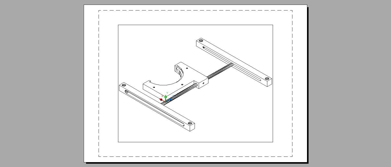
    You then have a thumb screw/Allen bolt on each end which you pinch up on the outside of the vertical slot to hold it in position.
    I'm not sure what is a pain to adjust there.
    Frikkin Lasers
    http://www.frikkinlasers.co.uk

    You are using Bonetti's defense against me, ah?

    I thought it fitting, considering the rocky terrain.

  2. #72
    Join Date
    Aug 2008
    Location
    UK
    Posts
    5,704

    Default

    The Thorlab screws I posted a link to above appear to consist of a threaded spindle and a fixed sleeve Norty.

    I was thinking if some way could be found to connect the screw spindle to the lens holder on one side and have a either a 2nd screw on the other side, or a simple hinge spindle, and a way found to retain the the fixed sleeve in a block within the vertical rail, then you'd have a precision adjustment system much like on a Thor lab mount.

  3. #73
    Join Date
    Mar 2007
    Location
    UK
    Posts
    244

    Default

    Looks like some good ideas on this thread.

    Maybe it would be a worthwhile exercise to define some basic metrics of what people have in their current projectors, so that the projector mounting element is not under or over designed, and can accommodate fitting to the majority of projectors without too much modification. e.g. scan aperture dimensions, location of scanner output in relation to this, if there are already any mounting holes on the projector, how much space is there surrounding the aperture etc.

    James
    Laser Safety
    https://www.lvroptical.com
    https://www.facebook.com/LaserSafety

    - Laser Show Safety Training & Audience Scanning Workshops.
    - Effects Assessment, and Realtime MPE Measurement
    - Pangolin PASS System Integrator

  4. #74
    Join Date
    Feb 2008
    Location
    East Sussex, England
    Posts
    5,248

    Default

    I've woken up with a vision of a hybrid design in my head. Something is nagging me about the 2 side bars, in as much as I think it's over engineered, and requires 4 mounting holes on the projector, where 2 should be adequate.

    I might fire up Google Sketchup and try and put something together (haven't used it in years!) but I guess we could share a file format a few people have access to between us so the various designs could be tweaked and a bit 'open source'
    Frikkin Lasers
    http://www.frikkinlasers.co.uk

    You are using Bonetti's defense against me, ah?

    I thought it fitting, considering the rocky terrain.

  5. #75
    Join Date
    Apr 2008
    Location
    Amsterdam, NL
    Posts
    2,098

    Default

    We have been using safety lensen long before Pangolin started to sell them. Some of you may even remember i had given lensen away at LEM for 5 euro a piece. (Funny thing is, no one wanted them)

    Anyway, we have done a lot of shows with safety lenses. We use a proven method to mount them. Its called gaffer tape just like pangolin on the PLS

    The tilt adjustment is not not needed if the hight of the diverged area is almost the same hight as the projector hight, so the line between devirged and undeverged is horizontal ( still with me?)
    Only when the laser is tilted (or projected) downwards tilt adjust is needed.

    The bottem line is in 90% of the shows we do, tilt is not needed and gaffer tape works perfect is my experiance.

    But if you want to have a fancy mount you could skip the tilt adjustment for most standard shows.

  6. #76
    Join Date
    Aug 2008
    Location
    UK
    Posts
    5,704

    Default

    I think the tilt is necessary with the 1/2 lens to prevent ghosting from memory. You can see this in the video at LSDI even with the projector mounted flat on a table. Not doubting what you're saying Maurice but there's obviously a difference between the lens. Maybe its the fact they're 1/2 lens as I seem to also remember some mention of internal reflection from the boundary.

    From this pov I'd definitely like to see a precision adjustment made possible rather than just a tilt and tighten philosophy.

  7. #77
    Join Date
    Aug 2007
    Location
    Under a rock in Cambridge UK
    Posts
    1,353

    Default

    Ok, this is by no means accurate, to scale or a proper engineering document... Just made in 5 minutes with PowerPoint, but you get the idea...

    The bottom part screws to the projector via the slot with two screws, the two uprights screw to the bottom part with 4 screws, allowing you to make sure they are vertical... This assembly gives your up/down and lateral movement... The lens holder is mounted into your uprights via two round rods fixed with grub or thumbscrews and this gives your tilting movement...

    Like I say, not a set in stone design, but a good start point... It's fairly elegant, not too complex and provides all axis of movement with easy adjustment...


    Click image for larger version. 

Name:	safety lens mount.png 
Views:	29 
Size:	135.4 KB 
ID:	36788

  8. #78
    Join Date
    Aug 2008
    Location
    UK
    Posts
    5,704

    Default

    Quote Originally Posted by andy_con View Post
    so something like this

    Andy, I think Maurice and Marc have the tilt design spot on hinging it at the top rather than the bottom.

    Thinking about it carefully, although a top hinge does mean the bracket needs to stand out further from the projector, there are 2 fundamental problems with a bottom hinge as in your original drawing:

    1. Safety - if the tilt screw should slip or work loose eg as a result of bass vibration, then with a bottom mounted hinge, the lens will swing downwards under gravity 180 degrees and finish up upside down and no longer over the aperture thereby exposing the audience to the un-diverged beams. With a top hinge arrangement, if the tilt screw should slip, the lens will just hang there vertically from the top hinge plate and will still cover the aperture.

    2. Horizon - With a bottom hinge arrangement, as you tilt the lens forwards you also bring the top edge of the lens and thus horizon downwards also. Although the distance may be minimal - perhaps only a few millimetres or centimetre at most at the projector end, it will throw the horizon lower in the room. This means re-adjustment of the vertical position following the tilt adjustment. If vertical adjustment affects the angle of tilt adjustment required due to the curvature of the lens and thus changing angle of incidence, then you could enter a cycle of constant adjustments between tilt and vertical plane. By contrast hinging the lens at the top, ensures the horizon is always maintained once the vertical adjustment has been set as its the bottom of the lens that moves up slightly, not the top that moves down.

    One further thought, although not to actual adjustment design, I think consideration needs to be given to lining the lens holder with something soft eg a very soft plastic or some other suitable material because at 100 Euro / Pound / Dollar per lens, they're very expensive to scratch and although it could be argued scratches on the lens edges won't affect the performance, if you have a hard material forming the actual lens cup part, then its only a matter of time before you catch the surface of a lens on it when fitting or removing the lens resulting in a very expensive mistake. To my mind, its better to design a soft non scratch holding cup from the start.

    I quite like Marc's design as its simple although I wonder how easy it will be to adjust 3 planes at once. It could be easier with more parts and thus screws controlling each piece.
    Last edited by White-Light; 02-02-2013 at 23:54. Reason: Quoted wrong post!

  9. #79
    Join Date
    Feb 2008
    Location
    East Sussex, England
    Posts
    5,248

    Default

    Actually, the design I'm fighting Sketchup with uses a bottom hinge AND is designed in such a way that it can't swing out of the way in the event something comes loose.

    I just need Sketchup to admit defeat, and let me do the things I want to do!

    Re: your point 2, the actual amount of tilt required to make the top edge parallel to the beam is inconsiderable in the situation you describe Al. We'll be talking centimetres difference, even at range, and you should have that sort of tolerance built in anyway to account for sway/vibration in the projector fixing system
    Frikkin Lasers
    http://www.frikkinlasers.co.uk

    You are using Bonetti's defense against me, ah?

    I thought it fitting, considering the rocky terrain.

  10. #80
    Join Date
    Sep 2010
    Location
    Utrecht The Netherlands
    Posts
    721

    Default

    McCarrot, any chance you have some lenses with you next Dutch Lem?

    Perhaps other attendees are also interested?

    Michel
    --------------------------------------------------------------------------------------------------------------------------------------------
    Michel Rietveld @ Utrecht The Netherlands

    FB3, BEYOND Ultimate, 3xFB4, apc 40

    1x5W RGB 637nm 1.3W, Edison Blue 2.5W 445nm and CNI 2.5W 532nm Greenie with Pico driver with DT40Kpro scanner set

    2x3W RGB DT30 scanner set

Posting Permissions

  • You may not post new threads
  • You may not post replies
  • You may not post attachments
  • You may not edit your posts
  •