Page 10 of 15 FirstFirst ... 67891011121314 ... LastLast
Results 91 to 100 of 149

Thread: Who 'd like test our dichoric

  1. #91
    Join Date
    Dec 2007
    Location
    Nottingham, UK
    Posts
    2,850

    Default

    Wavefront distortion results show an insignificant change.

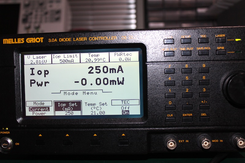
    I setup a single mode, generic red laser diode, at constant current and temperature (250mA, 21°C) and checked the beam in the far field with and without a dichro; I could not measure or visually discern a difference. (It's really not worth me posting two images of identical red spots.)


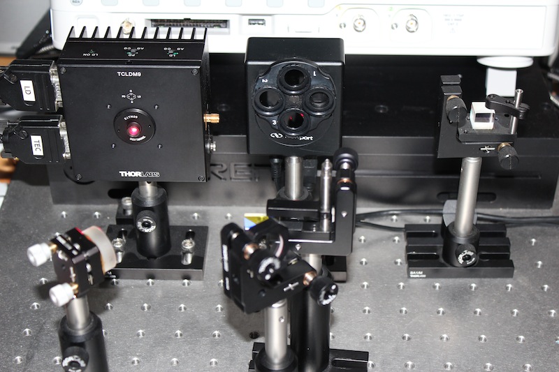
    Next I setup a much shorter throw shot, but with a CCD beam profiler (not exactly a Shack-Hartmann, as it lacks the micro-lens array) but the best I can do with my kit. Dichro insertion point from the CCD is 120mm [±2mm].
    The beam exits the diode housing, is bounced off a positioning mirror, and into a beam sampler; this reflects <1% on the CCD; the remainder is transmitted into a beam dump. Varying the AOI did not change the beam geometry, just the *very minor, and expected* displacement.


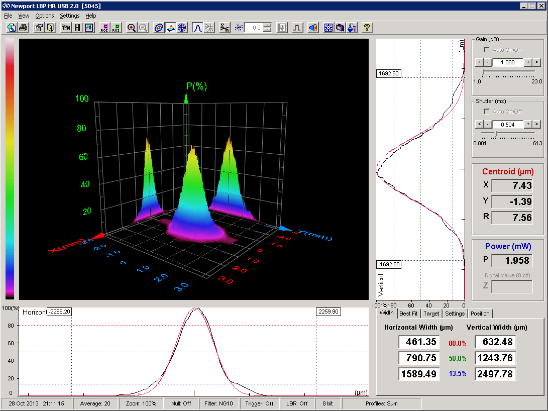
    The results show no change in beam geometry. (The exact difference can be attributed to electrical noise.) An obvious *small* beam displacement was detected.


    With NO Dichro:


    With Dichro B:

    - There is no such word as "can't" -
    - 60% of the time it works every time -

  2. #92
    Join Date
    Feb 2011
    Location
    New Hampshire
    Posts
    3,513

    Default

    Daniel,

    Once again, good work and an excellent presentation. Now, do you think you could look at the diode output stability on say... the femtosecond time scale??? I mean why not, huh?

    Junktronix,

    Good "digital" data

    The way I read these dichros is that they should be used G to R to B to scanner.

    Bridge,

    I for one like Daniel's broad band approach because the "445" nm lasers may vary significantly around 445nm and as far as I can tell his source is unpolarized. When you used the laser in the lab you may be getting readings that are more favorable due to the polarized source. A multiple diode module will have to live with the average reflectance measured by unpolarized light.

    Doc,

    Two part, hardware store, epoxy works well. Just use it judiciously. Alternatively, the one part silicone "aquarium sealant" also works well and has the added benefit that the acid it contains (smells like vinegar) primes the aluminum. In all cases, avoid getting the adhesives on the coatings. They work best when they back up a mechanical support rather than replace it.

  3. #93
    Join Date
    Nov 2008
    Location
    Cleveland Ohio
    Posts
    2,613

    Default

    ok what does 520nm look like for us dumb people? Are these the dichro we are after for 520nm?

  4. #94
    Join Date
    Feb 2011
    Location
    New Hampshire
    Posts
    3,513

    Default

    It looks nice. It is clearly not 532 even if they are not side by side. These will work for 520 as well as 532.

    Not having tested any others as thoroughly, it is impossible to say if these are the very, very best, regardless of cost, but they might be and if not, the room for improvement may be so small it makes little sense to spend much effort in the search.

    I have a new target...mirrors. For single color reflectivity @ 45 degrees I would just use the "wrong" dichroic because the reflectivity is so high. The problem is that Daniel's test reveled no wavefront distortion in transmission, but this is largely to be expected. It is in reflection that the distortion is likely to be seen. If these also perform well here then the only remaining need is a broad band HR mirror @ 45 degrees.

  5. #95
    Join Date
    Aug 2005
    Location
    Silicon Valley
    Posts
    442

    Default

    Here are a couple of shots of my test fixture


    The light source is coupled into the block on the right. There's a collimating lens there to reduce the divergence of the fiber output a bit. For transmission testing, the output fiber goes to the block on the left. For reflection testing it goes to the block at the back (as shown).

    Here's the spectrum of my light source.


    and the transmission spectrum with no optic in the fixture. Notice that the signal to noise ratio gets pretty bad in the blue wavelengths where there is a lot less signal, and the same amount of noise.


    Here are screen caps of the 2 dichros being tested


    Last edited by Junktronix; 10-28-2013 at 19:07.

  6. #96
    Bradfo69's Avatar
    Bradfo69 is offline Pending BST Forum Purchases: $47,127,283.53
    Join Date
    Jul 2010
    Location
    Wilmington, DE
    Posts
    6,206

    Default

    ('bout the only thing I understand in this thread is... you have a lab cat. )

    @planters - Would these still be ok for a G-B-R-> scanner set up?

  7. #97
    Join Date
    Feb 2011
    Location
    New Hampshire
    Posts
    3,513

    Default

    If you shot the red straight into the scanner through the transmit red dichro you could make it the last color, but you would have to use the other dichro to reflect the green into the blue first, so I would think B-G-R-scanner would work. As a general rule of thumb long pass filters work better than short pass or band pass. This does not mean you can't break this rule it is just easier for the filters to perform in this order.

  8. #98
    Bradfo69's Avatar
    Bradfo69 is offline Pending BST Forum Purchases: $47,127,283.53
    Join Date
    Jul 2010
    Location
    Wilmington, DE
    Posts
    6,206

    Default

    Ok. The projector I would like to replace the dichro's in is green -> blue -> red -> scanner. I don't want to reconfigure the projector and, it sounded as if these might work as an improvement. I just know I appear to have an awful lot of loss shooting through the dichros. It may not be as much as I think and, if I recall correctly it was maybe 50-100mw, as mentioned earlier on a 3 watt RGB. I "could" be wrong on that number.

  9. #99
    Join Date
    Jan 2007
    Location
    Peking
    Posts
    1,207

    Default

    our dichroic can using green -> blue -> red -> scanner and green -> red -> blue -> scanner, both are ok.
    because reflect blue the same time pass green and red, reflect red the same time pass green and blue.
    only green in first, the blue and red can change your places with you like. thanks.
    Best regards!
    Bridge
    QUOTE=Bradfo69;274361]Ok. The projector I would like to replace the dichro's in is green -> blue -> red -> scanner. I don't want to reconfigure the projector and, it sounded as if these might work as an improvement. I just know I appear to have an awful lot of loss shooting through the dichros. It may not be as much as I think and, if I recall correctly it was maybe 50-100mw, as mentioned earlier on a 3 watt RGB. I "could" be wrong on that number.[/QUOTE]
    Laser-wave can supply:
    Green 532nm, 4W, 10W, 15W
    blue 445nm, 2W, 3.5W, 6W, 10W
    blue 462nm, 2W
    Red 638nm, 500mW, 1W,2W, 4W, 5W, 6W, 8W, 10W
    All diodes, All optics, All mount, All laser base and housing for yourselves building lasers.
    Speical products, 532nm, OEM-V-SS, 4W, 98mm*46mm*48mm; OEM-H, 10W, 250mm*88mm*70mm
    www.laser-wave.com or www.laser-wave.net
    bridge@laser-wave.com or 463366312@qq.com
    We Chat: 463366312, Laserwave-Bridge

  10. #100
    Join Date
    Jan 2007
    Location
    Peking
    Posts
    1,207

    Default

    Thanks Junk, well working.
    From your graph without dichroic, we can see many oscillation around 400-480nm, which will make the test result not stability.
    Maybe you can help using your lasers to do some more test when you had time, thanks.
    Best regards!
    Bridge
    Laser-wave can supply:
    Green 532nm, 4W, 10W, 15W
    blue 445nm, 2W, 3.5W, 6W, 10W
    blue 462nm, 2W
    Red 638nm, 500mW, 1W,2W, 4W, 5W, 6W, 8W, 10W
    All diodes, All optics, All mount, All laser base and housing for yourselves building lasers.
    Speical products, 532nm, OEM-V-SS, 4W, 98mm*46mm*48mm; OEM-H, 10W, 250mm*88mm*70mm
    www.laser-wave.com or www.laser-wave.net
    bridge@laser-wave.com or 463366312@qq.com
    We Chat: 463366312, Laserwave-Bridge

Posting Permissions

  • You may not post new threads
  • You may not post replies
  • You may not post attachments
  • You may not edit your posts
  •