
Originally Posted by
buffo

Yes, it is normal for the negative color signals to share a common ground. Most controllers use a single-ended output for the color modulation signal, so the R-, G- and B- signals are already common to ground from the controller end.
You can do this, but a better method would be to use the keyswitch to control a triple-pole, double-throw relay and switch each one of the POSITIVE inputs to the drivers.
The idea is that in the de-energized position the relay would connect the positive side of the laser driver modulation inputs to ground, making sure that there is no possibility of laser output. (Certain laser drivers will allow some output if the positive modulation input is disconnected and left floating, so by crowbarring to ground you eliminate that possibility.)
When the relay is energized it should connect the modulation inputs on the drivers to the appropriate R+, G+ and B+ pins on your ILDA connector.
Here's a complete interlock schematic. Look at the relay contacts for Red, Green, and Blue and you'll see what I'm talking about. Note, however, that this circuit also includes a remote, a latching relay, a projector "start" circuit, and a few other features that you probably weren't planning to add to your projector.
Adam

 buffo
buffo

 Reply With Quote
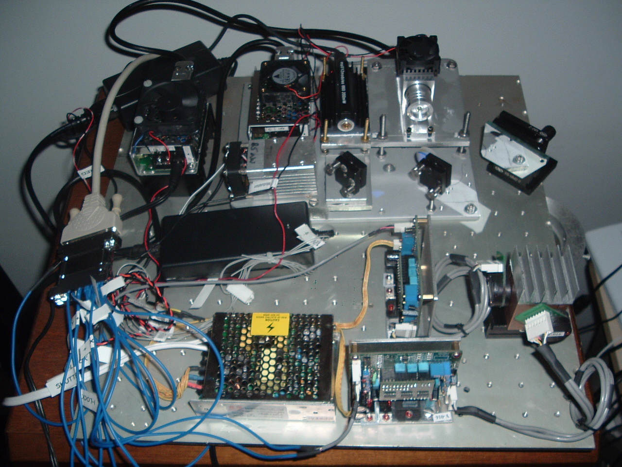
 My avatar picture is from some of the "first light" pictures that I took when I first powered up this test stand.)
