 FB3 hookup and initial results - help!!!
OKAY, I decided to use the "stock" FB3 connection to my scanners (ScanPro 30's), with no intermediate circuitry to complicate things.
Ignoring the interlocks and laser modulation inputs for the moment, the FB3 gives me the following connections across the ILDA connector:
X signal
X ground
Y signal
Y ground
Intensity signal
Intensity ground
My scanner amps have the following connections per amp:
(with power supply connected as indicated):
Signal in (-)
Signal in (+)
Signal ground
Scanner feedback
-24V
Gnd
Gnd
+24V
SO -
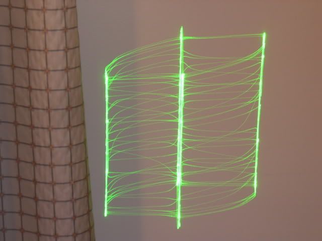
Can anyone who has hooked up the FB3, using similar connections, give a little tutoring on the proper connections to make here? I'm using the Pangolin LiveQUICK application with for my initial testing, with Buffo's recommended test frames from his scanner tuning tutorial. My initial displays have been nothing but an unrecognizable "glob", with VERY noisy scanners!! 
Any assistance (before I blow something up!!!) would be appreciated - I don't even want to attempt tuning until I'm sure everything is hooked up correctly!!
Thanks in advance!!
Randy
Last edited by Stuka; 03-16-2008 at 19:40.
RR
Metrologic HeNe 3.3mw Modulated laser, 2 Radio Shack motors, and a broken mirror.
1979.
Sweet.....


 Reply With Quote
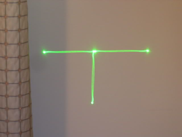


 buffo
buffo
