-

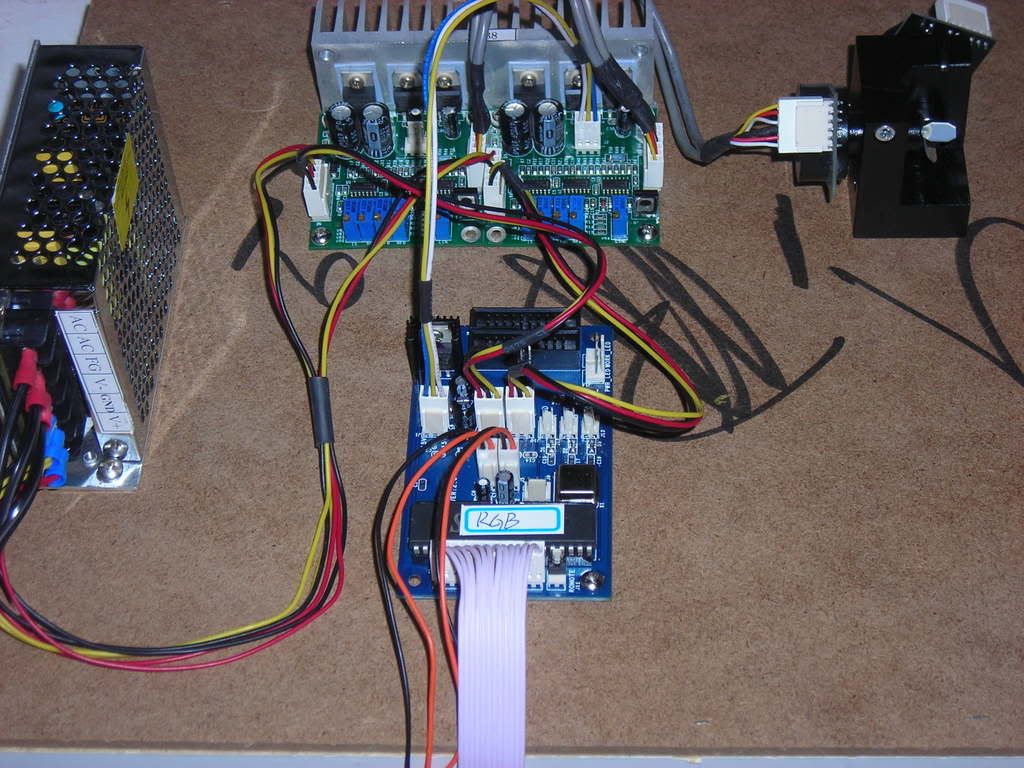
Even though both of your scanner amps are bolted to the same hunk of Aluminum, they are two separate devices. They should be exactly the same thing, but one is for X and one is for Y. You can clearly see that there are three pins for power and a bunch of pins for the input and a bunch of pins for the output ~ the scanners themselves. The inputs really only need three pins each, but they probably made them different from the power connectors so that you would not be able plug +/- 15 VDC into the inputs of the amps.
The DMX board is not only for automatic DMX control, but it also gives you a standard ILDA connector and routs all the signals to the right places. It looks like you have differential drive on the scanners, but only single ended signals for your red, green, and blue. No biggie!
You need three power cables coming from the PSU, each one terminating into a three wire socket that fits the power pins on each of those boards. They all get hooked up in parallel to the PSU.
Take some more pictures! What do the other ends of those cables look like? Where's the PSU? What about the scanners? Huh???
James. 
-
only a few more things to figure out....
-
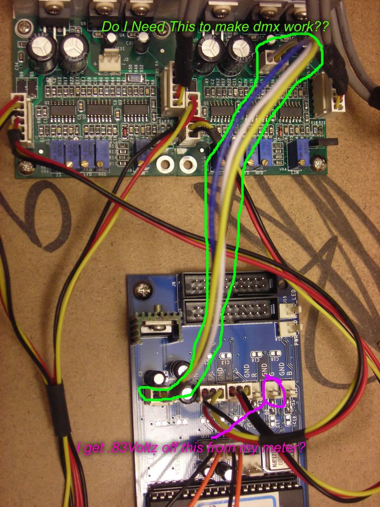
OK. I see now, your amp board input connector has both power and signal in it. That other thing that goes from one of the amps to the DMX board should also be power, but check it with a meter first!
Looks like you got it all hooked up right.
What's on the other end of the gray ribbon?
Now, how do you make the DMX thing go?
James.
-
grey ribbon cable has a dip switch for dmx settings,,, now I hope that the dmx pcb will do modulation for my laser ,,,, it reads 0.83volts on my meter??? how would I test it to find out???? thanks
-
I am not sure on the connections, but on the BLUE board, the connections you marked as .83 voltz or whatever, they go to the MODULATION IN on your laser modules! You can see them marked R G and B. DMX is for your DMX in, of course. As for the plug that says +15V, G and -15V that is your POWER IN for your DMX board.
-
You need to get someone else here on the PL to id that DMX board and tell you how to set the dip switches so that it goes into auto mode; i.e.: no external DMX signal required.
James.
-
Like this, and of course your DMX goes to the DMX in. Mind posting a pic of the WHOLE DMX/ILDA board, so we can see what all the connections are?

-
He doesn't have a source of DMX control signal to put into this board.
Do you know the dip settings to put this board into auto show mode?
James.
Last edited by James Lehman; 09-04-2008 at 09:46.
-
Well, if its a standard 10 DIP switch board, then usually all switches OFF is auto mode. On my scanpro's, with DIP switches 1 and 10 ON, it goes into sound active mode. THen again I cant tell if the board has sound activation from the pic, but all switches OFF should be auto mode
-
let me first start off by saying" I love you laser nerds!!!!! Thanks for helping me out ..... and yes my DMX board is sound auctive with a volume control..... and when shipped the dip switch was 1 & 10 on and the rest off... so maybe thats DMX sound reactive mode??? Im about to test it out!!!! I cant wait untill I go to LaserBoys house to get this bad boy up and running
 ........ YOU ALL ROCK.......

 Posting Permissions
- You may not post new threads
- You may not post replies
- You may not post attachments
- You may not edit your posts
-
Forum Rules


 Reply With Quote