Page 2 of 2 FirstFirst 12
Results 11 to 20 of 20

Thread: Polarizing vs Non Polarizing

  1. #11
    Join Date
    Dec 2006
    Location
    Netherlands
    Posts
    983

    Default

    Awesome rendering!
    What package did you use for that? I tried rendering laser beams in an old 3dstudio version once but didn't work out as well.

    You may want to reconsider using those fans though. They look cool but the airflow will carry dust and particles to your optics. If the diodes are mounted on a alu plate, cool it from underneath.

  2. #12
    Join Date
    Dec 2007
    Location
    Stockholm, Sweden
    Posts
    556

    Default

    Nice renderings, very cool project!
    I have a question, why use Aixiz housings when you are going through a lot of work making holders for them anyway? Just drill a 3,6mm hole in the aluminium and mount them directly.
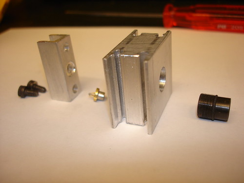
    I made a holder like this the other day:


    You can borrow my 9x0,5 tap set if you promise to take care of it! I'm located in Midsommarkransen by the way...

    At what current are you going to run them? I run mine at 126mA and it doesn't get hot at all in that heatsink.
    Last edited by dar303; 10-03-2008 at 05:13.

  3. #13
    Join Date
    Jun 2008
    Location
    Stockholm, sweden
    Posts
    352

    Default

    Quote Originally Posted by dar303 View Post
    Nice renderings, very cool project!
    I have a question, why use Aixiz housings when you are going through a lot of work making holders for them anyway? Just drill a 3,6mm hole in the aluminium and mount them directly.
    I made a holder like this the other day:


    You can borrow my 9x0,5 tap set if you promise to take care of it! I'm located in Midsommarkransen by the way...

    At what current are you going to run them? I run mine at 126mA and it doesn't get hot at all in that heatsink.
    The tap set i allready have actually.

    But the aluminium that you have there in the picture look really interesting. especially the big one.

    The aixiz housing where really cheap and i just bought them becouse really easy mounting.

    take care.

    /Rickard

  4. #14
    Join Date
    Dec 2006
    Location
    denver,co
    Posts
    1,078

    Default

    The renderings look great, what software? max? Any way that thing is going to be huge. Think about squashing things down as small as you can get. That is WAY more heatsink than you need for those. the v-reg on the driver is going to get much hotter than the diode. You will not need that many fans and heatsink area for that. Dar303s heatsink is WAY overkill for that diode also. As he mentioned it doesn't even get at warm at all.

    Here is what i was thinking for a mutiple led device. (c) chad

    The outside is 1.5" or 35mm The lenses are just a rough guessitamate for illistration. The theory saus if you can colimate a square array of lasers you should be able to do the same with a circular arrangement. This is for seven but could be scaled bigger easly. You also could polorize one of these horisontal and the other vertical and use a cube to combine the two and have 14*(~100mw) of 405. BTW. these are using the axixz lenses.

    chad

    P.S. Be sure to use real numbers in your render. It makes things much easier when you want to actually make physical things.
    Attached Thumbnails Attached Thumbnails 7 shooter1.jpg  

    7 shooter2.jpg  


    When the going gets weird, the weird turn pro.


  5. #15
    Join Date
    Dec 2006
    Location
    denver,co
    Posts
    1,078

    Default

    Here is a 12 version. I didn't put the other stuff in. Just pretend that it is all scaled. (solidworks is being buggy) and I Don't feel like fixing things.

    you will get the idea. Think small and cheap to make.

    The nice thing about this is if i had time i just could go to the shop and make it. The problem is i don't have the time.

    Also, here is a 500 mw duel red i was thinking about 2"x2" (24mmx24mm).

    chad
    Attached Thumbnails Attached Thumbnails 12 shooter.jpg  

    gangbang.jpg  


    When the going gets weird, the weird turn pro.


  6. #16
    Join Date
    Dec 2007
    Location
    Stockholm, Sweden
    Posts
    556

    Default

    Very nice! I had imagined a similar square setup but without you integrated adjustment screws for the PBS...that is a really smart innovation!

    Aargh, I must get my CNC-machine up and running soon!

  7. #17
    Join Date
    Jun 2008
    Location
    Stockholm, sweden
    Posts
    352

    Default

    oh..great. that is really smart chad.
    didnt think of that. really cool.

    (yep rendered without any filter or anything in 3D Max9
    its really cool that the "Max" actually blends the lights like in real life.
    would use autocad normally but the light is so much nicer in Max. )


    on the 6pieces what will the diameter be?
    going to check for the correct lens on monday

    great idea.

    Dar303... still interested where you got a hold of that alumium chunk?

  8. #18
    Join Date
    Dec 2007
    Location
    Stockholm, Sweden
    Posts
    556

    Default

    Oh, sorry!
    I collect a lot of "stuff" from discarded machinery etc. and these pieces is out of an old power supply, it had transistors mounted on four of these.
    they are a bit thick (15mm) for an aixiz clear acrylic lens to be easily adjusted, 10mm would be enough I think.

    I'm going to use aluminium bars to make more mounts of different sizes, I have some 10x20, 20x20, 30x30mm bars from automation equipment to cut up.

  9. #19
    Join Date
    May 2007
    Location
    Romania
    Posts
    1,041

    Default

    The obvious is put some other colours in that mount and have instant mixing.

    I did look at this early this year affter seeing a coherent donut.

    The one big problem i saw was as the diodes get hot the alignment could goes off.

    We thought to place a load of diodes on a bed in a circle all pointing to the center with each hitting an alignment mirror before the first lense, so as time goes on you still can adjust each beam.

    So each diode is placed like on a clock face number with its beam towards the center of the clock, then the mirrors near the center to bounce the beam out to wards you from almost the clock center. This way you could easly put 20+ diodes and still have adjustable beams.

    I also think with some cleaverness you could put a ring of red, a ring of blue and some greens on larger diamiters that all end up towards the center of the clock. Understand?

    Andy

  10. #20
    Join Date
    Dec 2006
    Location
    denver,co
    Posts
    1,078

    Default

    Yea I thought about a multi color version also. Just didn't draw it up. I did not think about the beam wandering when the temperature changed.

    chad


    When the going gets weird, the weird turn pro.


Posting Permissions

  • You may not post new threads
  • You may not post replies
  • You may not post attachments
  • You may not edit your posts
  •