stanwax
Sensible advice Josh
But at least being clear on how it should be wired up could negate the need for this
Rob

Sensible advice Josh
But at least being clear on how it should be wired up could negate the need for this
Rob
If you need to ask the question 'whats so good about a laser' - you won't understand the answer.
-----------------------------------------------------------------------------------------------
Laserists do it by the nanometre.
Stanwax Laser is a Corporate Member of Ilda
Stanwax Laser main distributor of First Contact in UK - like us on Facebook http://www.facebook.com/FirstContactPolymerCleaner
www.photoniccleaning.co.uk
 Senior Member
If it is the power supply, that would be nice. I can make those. I can't replace an 8 anode 808nm diode. I wouldn't even know where to look for one. Anybody got a few laying around? LOL
Not sure if it is in a bar or stacked offset. How can you tell?
John
you probably cant tell what the diode is like easily with the optics in front of it attached to that ally plate (the one with the black screws and grey cement). This will be a microlens holder which is an alternative to having the microlens attached directly to the diode. As for having one lying around - you would be able to get one - for a price (and it wont be cheap - I would hazard a guess, if it is 10W, that it will be >$500 probably more if its a well known brand such as SDL. But lets not jump to conclusions - I have no problem beleiving that it was working when pulled by Kyle so there is no real reason to assume its dead while it looks likely you have it wired up to PSU incorrectly.
Rob
PS swapping the diode would be pretty simple....its realigning the cavity afterwards to get the desired quality and quantity of light output that would be tricky - especially with WATTS of IR floating about!
If you need to ask the question 'whats so good about a laser' - you won't understand the answer.
-----------------------------------------------------------------------------------------------
Laserists do it by the nanometre.
Stanwax Laser is a Corporate Member of Ilda
Stanwax Laser main distributor of First Contact in UK - like us on Facebook http://www.facebook.com/FirstContactPolymerCleaner
www.photoniccleaning.co.uk
Senior Member
WOW!!!!! That has to be the most wicked C mount I have seen 5mm thick????? I would love that laser here for repair! I have several 20 watt bars that would fit nicely into that! The FAC lens is a LIMO unit. Very nice.
You are the only one that can make your dreams come true....and the only one that can stop them...A.M. Dietrich
Senior Member
John,
I sent you the additional documents to your email... did you get them?
I have not heard back from you.
Kyle
www.laseronics.com
Member
Here's a sketch of how I remember the power supplies - I'm not 100% sure if it's right, so it would be a good idea to use data from Kyle / the manufacturer.
I think the diode current for a 400mw blue was 7.5 amps.
B.
Member
Oh, yeah,
the bit about the floating 5v supply refers to sketch - if the 5v supply has it's negative output ( labeled 0v) tied internally to mains ground , and the 12v supply does too, then unpleasant fault currents would flow between the two. If the 5v supply does, but the 12v one doesn't, then the fault current might flow through the source of the Modulation ( FB3/pangolin/whatever).
5v@40amps can make short work of most PCB tracks.
B.
Last edited by fuzcub; 10-10-2008 at 16:57.
Senior Member
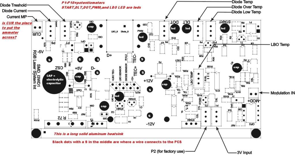
Thanks fuzcub. I am going to post a pictorial of the driver board from KYLE that he sent me. Also a picture of the driver board. Josh is actually going to do the posting as I haven't figured out how to do it here yet. I am not using a separate -5v voltage input . With my 5v bench supply, its 5v+ goes to the 5v+ input on the PCB, and its 5v- goes to the 5v- input on the PCB.Originally Posted by fuzcub

What do you guys think now?
Thanks,
John
Senior Member
Fuzcub:
So you think I should connect 12v- and 5v+ together external to the PCB? I don't see any separate 5v- supply. I don't see a split rail here. Am I wrong?
John
Last edited by Docjohn; 10-10-2008 at 19:16.
Senior Member
uploaded for john
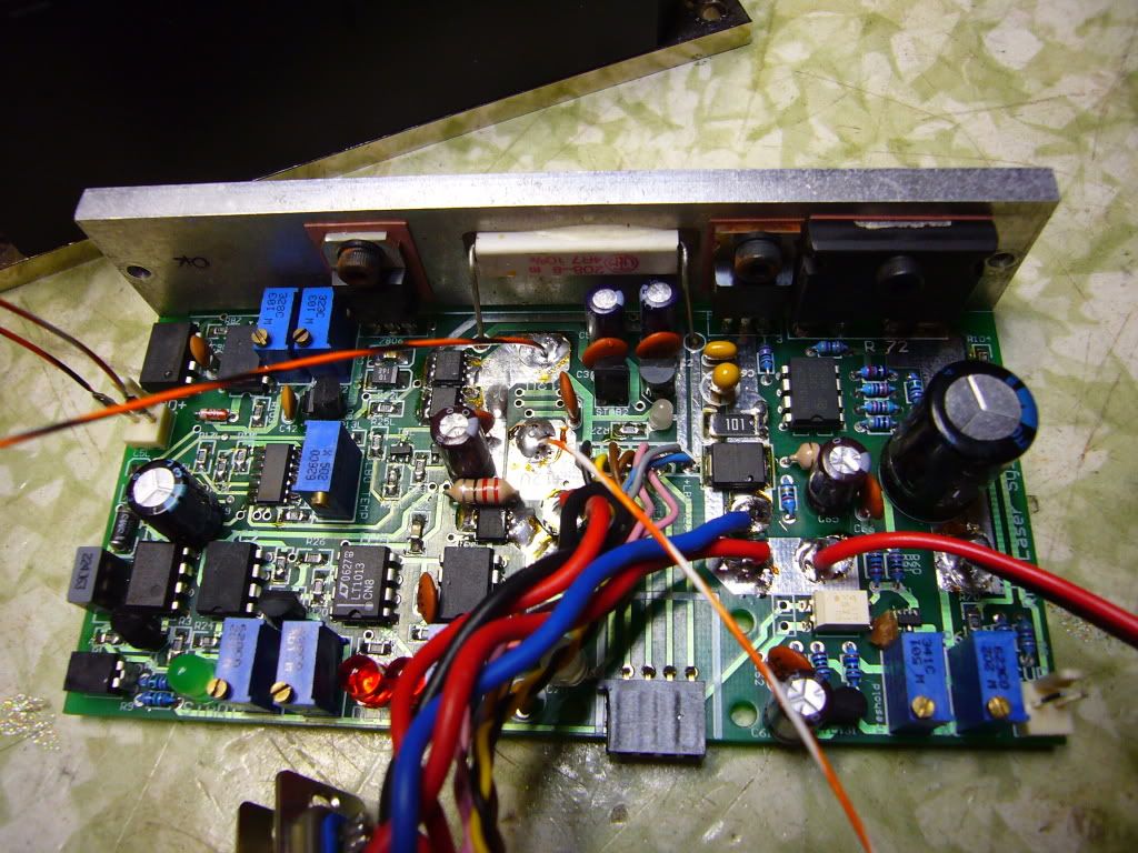
-Josh

 Posting Permissions


 Reply With Quote