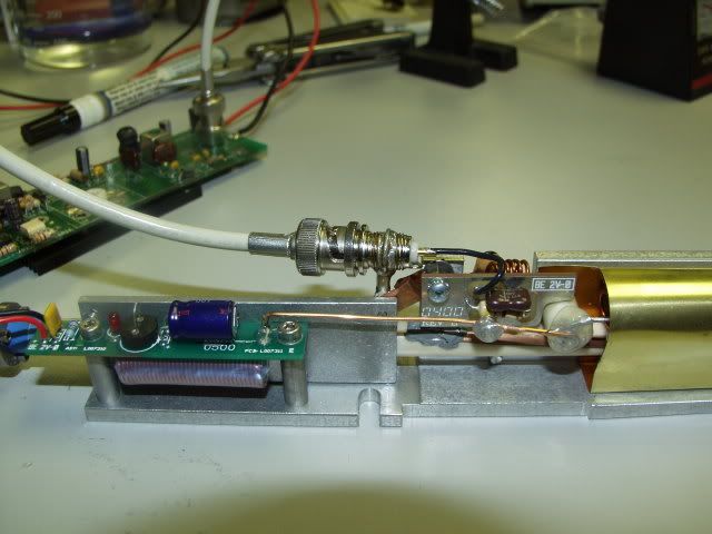
OK the fuse is 15A 250V fast acting, sort of odd package type one. The red and black are 36V at about 10A in 12V on board is 12V at about 5A or so, and the 5V input is 5V at about 300mA. The RF preamp board must be grounded and heat sunk or the medium power Rf transistor will fry. Make sure the RF power fet has a fully wetted solder connection and good ground/heatsinking to the laser tube or it will self-destruct

 Reply With Quote
 300EVIL


 Mix it with that Ruby?
  Be an intersting optic.
 ")