Page 4 of 7 FirstFirst 1234567 LastLast
Results 31 to 40 of 70

Thread: Start of the 5Watt project

  1. #31
    Join Date
    Feb 2005
    Location
    Switzerland
    Posts
    1,411

    Default

    I could be wrong, but isn't already an embeded resistor on the driver to absorb that extra voltage (power supply's voltage minus diode's drop voltage), and so the driver gives only the adapted voltage to the diode (since it is current limited), no matter the power supply voltage?

    If so, the series diode should be there only to even out the current draw between the diodes (since diodes are always slighty different, electricaly speaking), and consequently the resistor can be a lot smaller...

  2. #32
    Join Date
    Oct 2006
    Location
    Cleveland, Ohio
    Posts
    2,342

    Default

    For driving PHR diodes in parallel you would want around 15 ohms, 1/3 to 1/2 watt metal film (thick or thin film) 1% (thermally stable) resistors.

    Remember to keep the wires as short as possible.
    For only 5 diodes in parallel the max current out of the driver will be about 600mA (120mA each). The bias current should be about 100mA (20 mA each).

    Nice to see you building a multi-blu, looking forward to the final result

  3. #33
    Join Date
    Dec 2007
    Location
    Nottingham, UK
    Posts
    2,849

    Default

    Just a quick question or two:

    Quote Originally Posted by drlava View Post
    Remember to keep the wires as short as possible.
    Is this to minimise inductance in the wires? What effect will this have? i.e. what would happen if the wires were 50mm long or 500mm long?
    Is it down to the high frequency modulation?

    Also, if one of the diodes were to blow, would it take out the others? I know we're not talking christmas tree lights here, but I mean more of the fact that it could set off an domino effect, which would blow them all. i.e. A blown diode may not draw the same current, or perhaps change its resistance slightly causing the others to draw more and more etc.

    Recently I was looking at doing something very similar, so I'm just curious

    Dan

  4. #34
    Join Date
    Oct 2006
    Location
    Cleveland, Ohio
    Posts
    2,342

    Default

    Yep it's to minimize the wires inductance. 50mm is very short, it's all laid out in the instructions for the driver. Just don't use 2 foot wires lacing around everywhere

    As I've said before, I've never seen a diode blow open circuit due to normal use, they pretty much always blow the OC facet and keep very close to the same voltage drop which would not endanger the other diodes. If one or more blows open circuit then the other diodes would share the drive current and all the issues that go along with that.

  5. #35
    Join Date
    Jun 2008
    Location
    Stockholm, sweden
    Posts
    352

    Default

    Quote Originally Posted by drlava View Post
    For driving PHR diodes in parallel you would want around 15 ohms, 1/3 to 1/2 watt metal film (thick or thin film) 1% (thermally stable) resistors.

    Remember to keep the wires as short as possible.
    For only 5 diodes in parallel the max current out of the driver will be about 600mA (120mA each). The bias current should be about 100mA (20 mA each).

    Nice to see you building a multi-blu, looking forward to the final result
    Thank you Lava

    i have found 2 that are near what you suggest. wich would you say suits best.

    Resistor1:
    Res. 15ohm 1% 0,6W
    Manufacturer: Vishay0.6 W precision type metal film resistor with small dimensions for common use. Can be machine mounted and processed using cutting and bending machinery. Tolerates detergents according to Mil-Std-202E.215 and IEC 60068-2-45.

    Power rating: 0.6 W (Tamb = 70 °C)
    Tolerance: ±1 %
    Temp. coefficient: ±50 ppm/°C
    Max oper. voltage: 350 V
    Dimensions
    body: Ø2.5×L7.0 mm
    wire: Ø0.58×L22.5 mm
    Packaging: Bound in ammo packs containing 1000 pieces.

    -----------------------------------------------------------
    Resistor2:
    Res. 15ohm 1% 0,6W
    Manufacturer: Vishay0.4 W precision type metal film resistor with small dimensions for common use. Can be machine mounted and processed using cutting and bending machinery. Tolerates detergents according to Mil-Std-202E.215 and IEC 60068-2-45.

    Power rating: 0.4 W (Tamb = 70 °C)
    Tolerance: ±1 %
    Temp. coefficient: ±50 ppm/°C
    Max oper. voltage: 200 V
    Dimensions
    body: Ø1.9×L3.4 mm
    wire: Ø0.45×L24.5 mm
    Packaging: Bound in ammo packs containing 1000 pieces.


    I would go for the 0.4W, if i would make a guess but i dont like to guess in this position

    thnx for your time,

    /Rickard

  6. #36
    Join Date
    Oct 2006
    Location
    Cleveland, Ohio
    Posts
    2,342

    Default

    Yep the 0.4W is a good choice

  7. #37
    Join Date
    Dec 2007
    Location
    Nottingham, UK
    Posts
    2,849

    Default

    Quote Originally Posted by drlava View Post
    Yep it's to minimize the wires inductance. 50mm is very short, it's all laid out in the instructions for the driver. Just don't use 2 foot wires lacing around everywhere
    But what would actually happen if you used long leads to the diodes?

  8. #38
    Join Date
    Oct 2006
    Location
    Cleveland, Ohio
    Posts
    2,342

    Default

    If you used long leads you could induce oscillations at the edges of sharp modulation changes. If you used really long leads then the inductance could cause self-sustaining oscillations which would blow the diode.

  9. #39
    Join Date
    Jan 2007
    Location
    Cupertino, California
    Posts
    2,130

    Default

    Are those mounts milled, like in a mill, or drilled on a drill press. The reason I ask is because it looks like some are at different heights which could cause a problem.

    Quote Originally Posted by rfourt View Post
    Hehe hey man. yea i saw your pix. looks great. are you using Bridge (Laserwave) beamcube? how much loss are u getting?

    Yea more pix wil follow every weekday.


    Hejsan (hello in swedish)

    Thank you. hehe.. yea the Drilling is going to be a workalnighter. :P

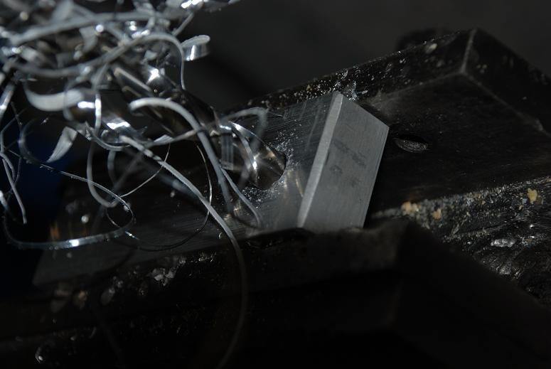
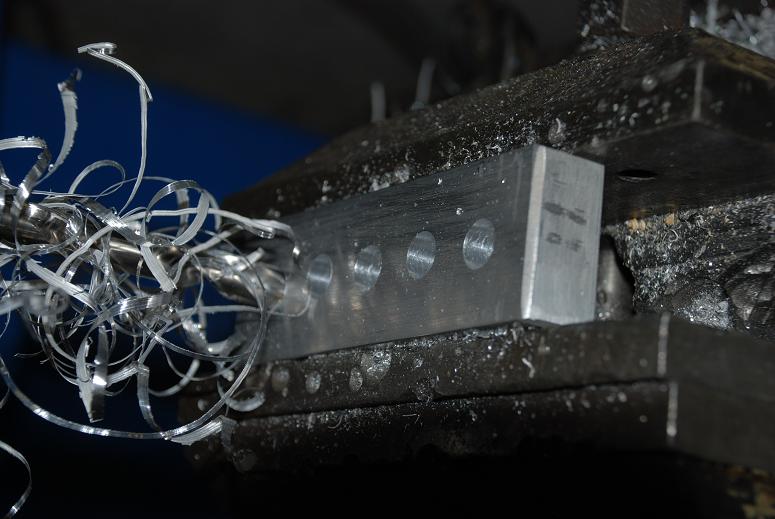
    When i ordered the alu-plate from our doughter company they asked if i wanted it processed with holes etc, They have a huge "MEK" processing machine up there but i didnt know the messurement and the distance beetwen the holes at that time so i will suffer, or i should say my drill´s will.. hehe..

    Yea for sure. mayby sometime late this summer would be an idea.
    NLM (Nordic Laser Meet)


    I will defenatly buy a 473nm sometime in a near future, although anything under 300-500mW is not interesting for me, and with the price´s at those powers is huge i cannot afford it right now.

    As i have heard if the Blue-rays are outputting 1Watt there is no more UV that is transmitted, (i could be wrong on this but i think i read it here somewhere) Although 1Watt of 405 is alot and sequrity will be my second name.

    But it will look beutiful 1.5meter above the crowds head anyway.


    Thank you.

    The material is aluminium and the name is international i think: "Alumium Profile bars"

    I was planing on buying the from "Thorlabs" at first but found a swedish company that sells these for the half price of thorlabs (exact the same quality specs) here they are on thorlabs: http://www.thorlabs.com/NewGroupPage...ctGroup_ID=194

    Although i know there are an US company selling the same on Ebay so go and search for "Aluminium Profile" there and you will find some.

    I Can really suggest using with these when building an enclousure. Really easy and fast. I think the chassi took me about 2hours with sawing and mounting. and its really stable and its leveled. and the weight is nothing.


    Ok thank you.
    can anyone with FB3+LivePro confirm that this is possible as this is probably the software package i will go for.

    Tank you all else for the nice comments makes me happy and keep the spirit up.

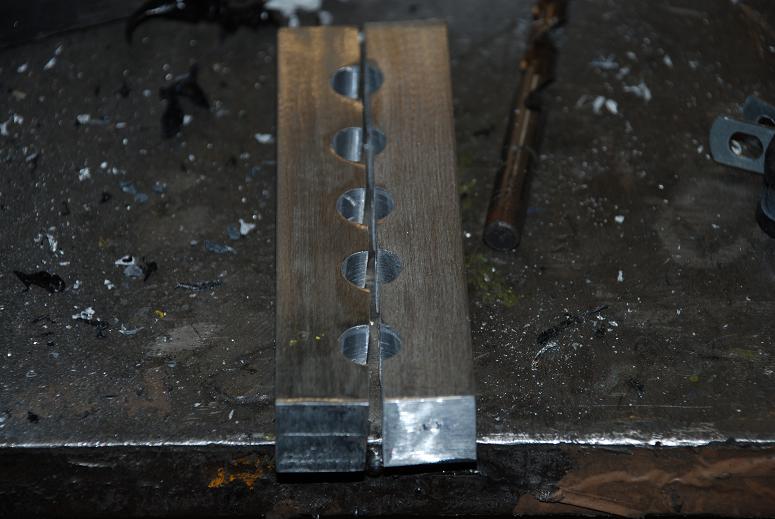
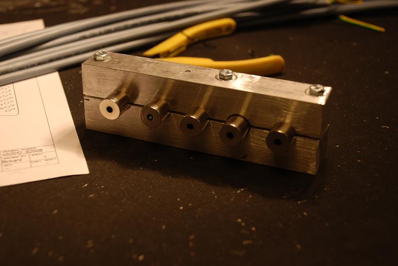
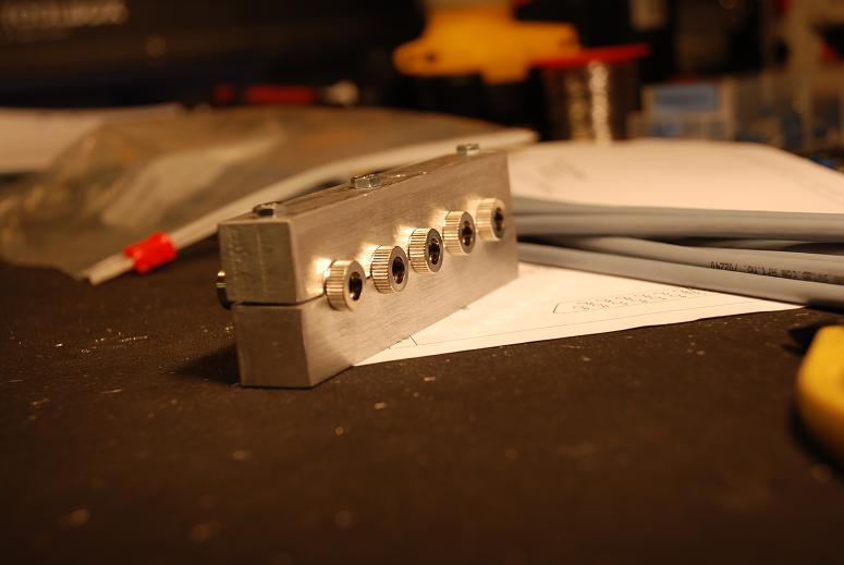
    As i promised here are some more pictures from the Diode mounts for the PHR diodes that im workin on.


    Split them in half to make it easy for adjustments and mounting/maintaince.


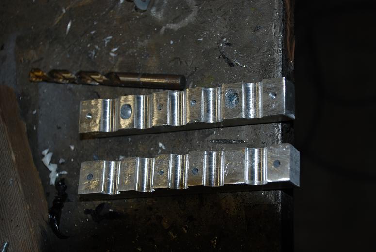
    Mounted with 5xPHR diodes and DrLavas Flex1 driver ontop.
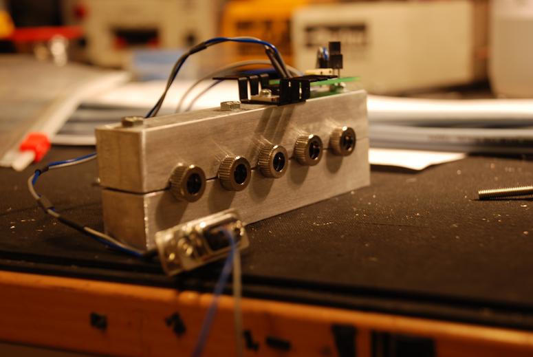
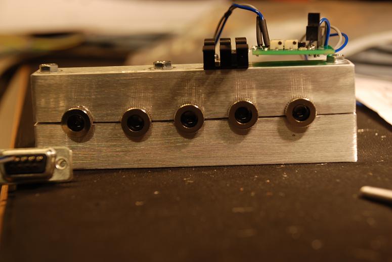


    M4 screws in place.


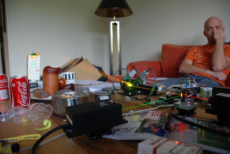
    A friend resting after a tuning sessions with 1 of the 2 LaserWorld scanners.


    Will see if i get anytime tomorrow to grab some more pics, dont know if i can stay after work and do some on the project as it is friday and with the lady home waiting and valentines day coming up this weekend she probably demands me home.. But will continue on Monday again.

    Thank again for all comments.

    be safe all

    /Rickard

  10. #40
    Join Date
    Jul 2008
    Location
    Rotterdam, Netherlands
    Posts
    789

    Default

    Quote Originally Posted by Laser Ben View Post
    Are those mounts milled, like in a mill, or drilled on a drill press. The reason I ask is because it looks like some are at different heights which could cause a problem.
    That doesn't look like a milling machine to me...
    And the second "problem" is the way the allu is clamped in the vice.
    It is not horizontal/flat...!!!
    The leftside is lower than the rightside... those holes can't be straight when you drill that way.

    Hopefully you still can allign the lasers.... but i think you will have alot of headace/problems doing it..

Posting Permissions

  • You may not post new threads
  • You may not post replies
  • You may not post attachments
  • You may not edit your posts
  •