Page 1 of 5 12345 LastLast
Results 1 to 10 of 44

Thread: PWM Woes....

  1. #1
    Join Date
    Jul 2008
    Location
    Marysville, WA
    Posts
    855

    Default PWM Woes....*more problems*

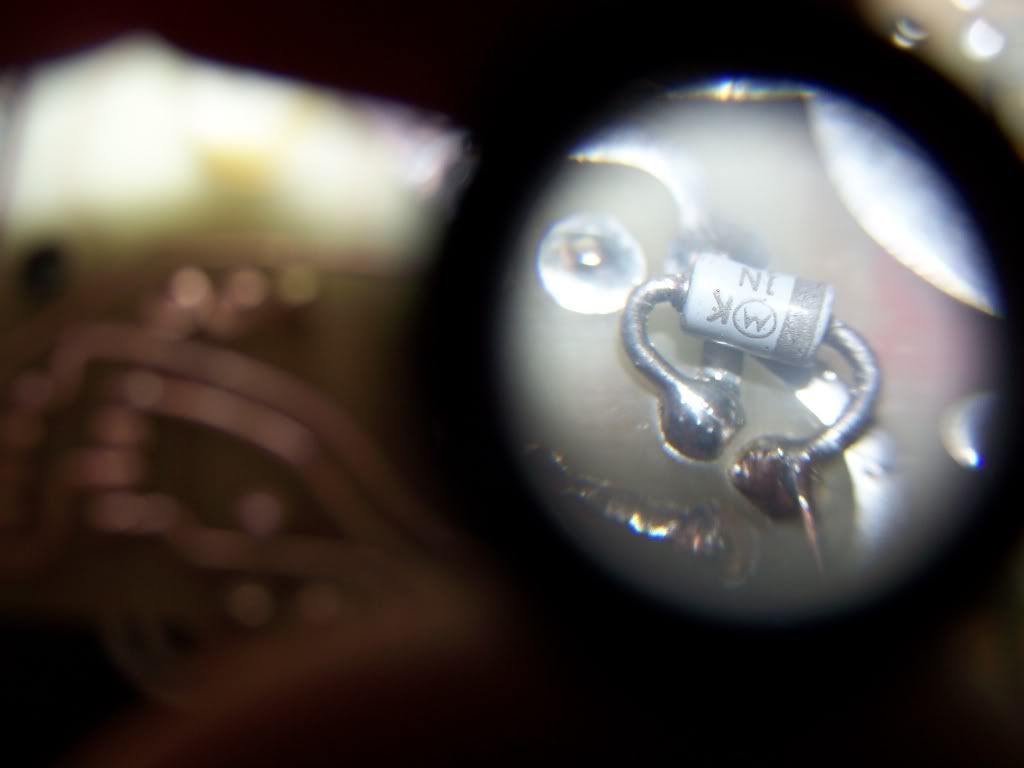
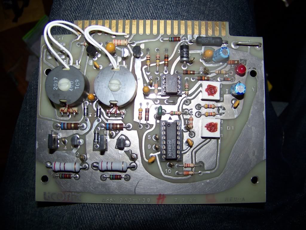
    So for some reason, my power supply for my HeCd laser keeps eating PWM cards... I'm thinking that the problem lies in the main 'driver' IC, which is the long IC in the picture below. Everything else on the card is pretty basic... resistors, caps, a couple little transistors. The IC is the only thing I could think of that would completely stop all function. The smaller IC is a little op-amp.

    Anyway, one card failed about two months ago, I swapped it with a spare that I had and everything was fine. Then just today another one died. I swapped in the last spare that I had and it's happy again, but I would like to rebuild these two 'bad' cards that I have, just to have them around and functional in case I need them.

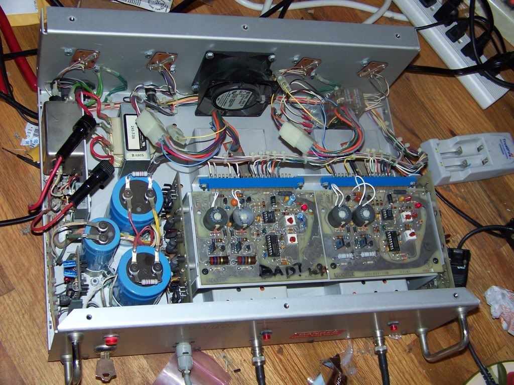
    The design looks very simple, each card (there are two in the supply, for the two separate HV units) is tied to a pair of power transistors which then power the HV module.

    Does this IC seem like the most likely component to fail?

    Any of you electronics gurus have any tips? The ICs are still being made (scratch that... no longer made but I found a couple for $2ea) and they are socketed so changing them will be very easy.

    There are no symptoms, it will work flawlessly one day and the next day one side of the PSU just wont work. Sometimes after that it will decide to randomly work, but that's rare.
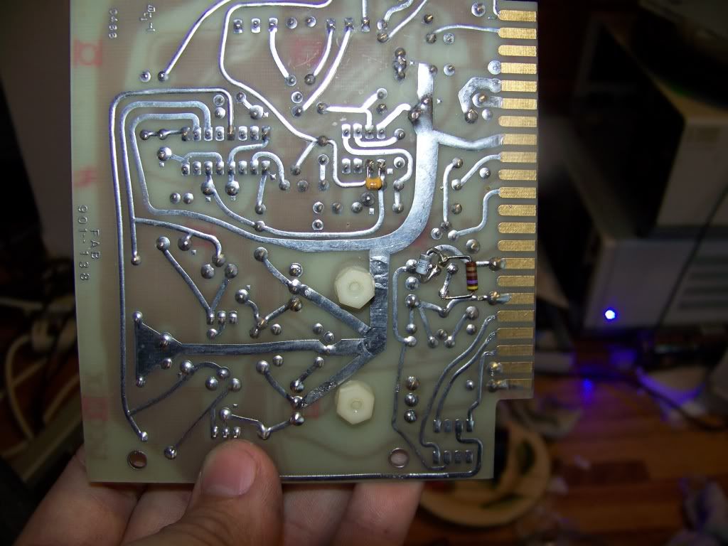
    Here's the board:

    Last edited by GooeyGus; 05-05-2009 at 16:01.

  2. #2
    Join Date
    Jul 2008
    Location
    Marysville, WA
    Posts
    855

    Default

    I know there are at least a few people here who might have an idea... dont be shy

    Steve R, Dr. Lava, I'm looking your way!!

  3. #3
    Join Date
    Oct 2006
    Location
    Cleveland, Ohio
    Posts
    2,342

    Default

    hey there, if it's 'eating' these cards and it didn't used to, I'd tent to suspect something connected to the card, not the card itself, is the cause of failure. Bad caps or surge supressors allowing voltage transients to the pwm card or something. But for the cards that have failed, you're probably on the right track, ICs tend to be the most sensitive. That is one old school looking card you have there.. hard to beleive it was made in '81 !

  4. #4
    mixedgas's Avatar
    mixedgas is offline Creaky Old Award Winning Bastard Technologist
    Infinitus Excellentia Ion Laser Dominatus
    Join Date
    May 2007
    Location
    A lab with some dripping water on the floor.
    Posts
    10,016

    Default

    Quote Originally Posted by drlava View Post
    hey there, if it's 'eating' these cards and it didn't used to, I'd tent to suspect something connected to the card, not the card itself, is the cause of failure. Bad caps or surge supressors allowing voltage transients to the pwm card or something. But for the cards that have failed, you're probably on the right track, ICs tend to be the most sensitive. That is one old school looking card you have there.. hard to beleive it was made in '81 !
    -----------------

    I'd tend to agree with my esteemed Colleague,

    It took less then 3 seconds to realize the words "Gate Driver" when looking at that card. HeCad supplies are nasty and like to kill themselves, 22 Kv or starting, 1500-3200 V running @ 60 mA, and seem to have a tendency to get power "reflected" from the load like it was RF and bad SWR.

    It is a protective device somewhere failing. You have two inductors there that do gate drive or base drive for the switching devices, which I'd guess are a pair of big PNPs, that doesn't quite look modern enough to be FETS.

    Since the first thing close to the chip that can create reflected or undamped power is those two inductors, which get some really meaty fast pulses running through them, I'd look at what drives them, those around the two transistors, next to the coils. Ie bad cap, marginal clamping zener or TVS diode. O'd then look at the next components in the power stream and the protective stuff around them. Without a schema I can only speculate, but it is informed speculation.


    For a example of a similar circuit, Take a look at the gate drive circuit in the Omni 150 schematic in the FAQ, your dealing with what looks like two of those stages, with pulse transformers being those two ferrite pot cores on the board. See if the pot cores are inductors or transformers. Based on the date of the technology, I'd guess the later. And these days I tell everyone to look at B+ (or B-) on the drive card circuitry as well and see if its clean. If you use a scope, and it had best be a cheap scope, use a 10-1 probe and "Lift" the scope from ground with a isolation transformer, and keep the scope limited to the drive card. You never know who used a "Hot Chassis" scope blowing design "feature" in that era, most switchers were. Those two parts are socketed for a reason, and it is not because someone at Liconix owned stock in Augat, who made the sockets.

    BTW, cheap pwm chips had a lot of variability then, does it seem quiet and happy when it runs?

    Those hecad supplies are nasty in terms of potential lethality, BE CAREFUL!

    Steve
    Last edited by mixedgas; 04-23-2009 at 03:15.

  5. #5
    Join Date
    Jul 2008
    Location
    Marysville, WA
    Posts
    855

    Default

    Well in the first 5 minutes or so of run time one can hear a high pitched switching that goes away. That was with the old card... Since I threw in the replacement it seems quiet from the start. I ordered two of the ICs so hopefully if it goes tits up again that will patch me up. I think board that brings power to the pwm card LOOKS ok... But that doesn't mean anything. I'll snap some pictures of it. The weird thing is that it hasn't been the same side to die. It was one side then the opposite side. I have an entire psu of spare parts, should I need them.

    I can't say if this supply has had problems with the cards before, as I haven't really had it long enough. I know that both of the original pwm cards bit the dust and I took the two out of my parts supply to get it working again.
    Last edited by GooeyGus; 04-23-2009 at 08:52.

  6. #6
    Join Date
    Jul 2008
    Location
    Marysville, WA
    Posts
    855

    Default

    well the replacement also failed to work today... Just quit working.

    I started swapping IC's from 'good' to 'bad' and eliminated them as the cause. Since the problem is the same on all three cards and seems to be intermittant on at least two of them, I had a feeling the IC's probably weren't to blame.

    I also elimated the big transistors, and the HV modules as cause of the problem by various tests.

    At this point I was just frustrated... I pulled out the DMM and literally began measuring every component's resistance to see if I could find something broken. I finished the entire board, comparing all compoents on the 'good' to one of the 'bad' boards.

    Everything was the same. No problems found.

    Then I flipped the board over... there is NOTHING on the other side except a tiny cap, a tiny resistor, and a tiny zener diode between two legs on a little transistor-looking component.

    As I understand zener diodes, resistance should rise while measuring them, as when they see voltage the resistance increases (or the other way around...) correct?? This is how the diode on the 'good' board was reading.

    Then I had an epiphany... all three of the diodes on the bad boards read as almost a short... .002 megaohm either way, no rising or falling of resistance. The 'good' diode would start at like .1 megaohm and climb up to at least .6 Megaohm before I got tired of measuring. So At this point I took the board which was the 'most' intermittant and put the leads on the diode, same thing .005megaohm and no change. Well after about 4 minutes resistance actually began to increase and from there on it appeared to be working. I had an idea at this point... I plugged the card in and it worked.

    So now the laser is working... lasing away, and it seems I need to order a few zener diodes to fix these boards.

    I dont know much about PWM... does this sound like a feasable problem? Out of however many components are on the board... probably around 100, this was the only component that I could get a reading different from the 'good' board.

    EDIT: Part number is a 1n4743A
    Last edited by GooeyGus; 04-23-2009 at 16:43.

  7. #7
    mixedgas's Avatar
    mixedgas is offline Creaky Old Award Winning Bastard Technologist
    Infinitus Excellentia Ion Laser Dominatus
    Join Date
    May 2007
    Location
    A lab with some dripping water on the floor.
    Posts
    10,016

    Default

    1n4743 is a 13V planar zener. Odds are its a clamp if as you say, its across a transistor. Just as predicted by Dr Lava.

    easy test, find a 15V power supply or use the 30V power supply from your galvos, hook a 1/2 watt 470 ohm or similar resistor in series with the zener and wire it across the power supply. Your meter , when across the diode, should read about .6 to .8 Volts one direction (forward biased) and 13V +/- .1 or so (ZENER ) the other. At 30V with a 470 ohm R, thats 60 mA through the device, a little high, but still a good test. Rated I Surge is 340 mA and rated current is 64 mA, A 640 ohm would be OK as well. At 15V its 31 mA, well within the ratings.

    Whats the number on la bete noir avec sa deux pieds?

    Happy ST George's Day,

    Steve

  8. #8
    Join Date
    Jul 2008
    Location
    Marysville, WA
    Posts
    855

    Default

    Whats the number on the black animal with two feet? Lol.... The number on the transistor-looking component which the zener diode is soldered to is..... lemme grab a lens so I can read it...

    Looks like a Motorola 2N6028

    If that's what you even meant :P

  9. #9
    mixedgas's Avatar
    mixedgas is offline Creaky Old Award Winning Bastard Technologist
    Infinitus Excellentia Ion Laser Dominatus
    Join Date
    May 2007
    Location
    A lab with some dripping water on the floor.
    Posts
    10,016

    Default

    Quote Originally Posted by GooeyGus View Post
    Whats the number on the black animal with two feet? Lol.... The number on the transistor-looking component which the zener diode is soldered to is..... lemme grab a lens so I can read it...

    Looks like a Motorola 2N6028

    If that's what you even meant :P
    Mais Oui. and its "black bug"...

    Thats a unijunction transistor. Are you sure they are only using 2 legs?

    Steve.

  10. #10
    Join Date
    Jul 2008
    Location
    Marysville, WA
    Posts
    855

    Default

    Well.. they are using all three legs of the transistor, the zener diode only directly contacts two but I think a resistor joins it to the third. Yup.. that's how it works. Zener goes from one pin to the middle, and then a resistor goes from the middle to the third. Here's a picture:


    You can see the laser in the background on this one hehe... shining on a broken HGM5


    *notice both cards lit up and everything working in this pic.... I'm sure it wont be like this tomorrow


Posting Permissions

  • You may not post new threads
  • You may not post replies
  • You may not post attachments
  • You may not edit your posts
  •