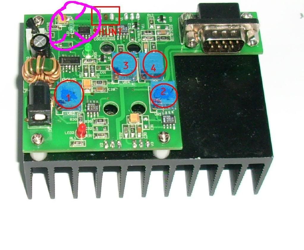
The shunt is a 0,33 ohm TO220 style resistor,
The green component is a coil / choke

 Senior Member
The shunt is a 0,33 ohm TO220 style resistor,
The green component is a coil / choke
Senior Member
A very intuitive read
Has anybody else "tweaked" their 473 and got results anything like GooeyGus?
Jim
Senior Member
You guys are telling me that this component is not a resistor???
Last edited by GooeyGus; 07-17-2009 at 11:55.
Senior Member
My 100mw did 150mW when I received it.
After my Tec opamps died I had to re-adjust the laser and its a VERY VERY VERY VERY VERY x 100 time consuming job.
I'm now back at 140mW, but after 1 hour it dropped back to 120 so still some work to do.
To find the optimal setting from scratch reserve about 8 hours of tuning.
Senior Member
Senior Member
I guess ya learn something new every day!! I thought it was just some sort of crazy green chinese resistorOriginally Posted by mccarrot

Hey, what is the resistance accross your shunt?
edit: you already answered. Just saw that :P
hmm... mine is a 1ohm. so I would calculate current differently then, yes? Would it be mV x 100?
Senior Member
If you check the screen print on the board you will see it has the prefix "L" which is for an inductor, resistors are prefixed "R".You guys are telling me that this component is not a resistor???
Jim
Senior Member
Yes sir! I knew about the labelling, I've really just never seen a coil in that package (but I dont work with much (any) RF stuff at all). It was labeled "LO" so I was hoping they gave it a weird label because it may have to do with current limiting. I just noticed mine was a bit different than the one in the photo. My driver will only go to a few hundred mA's, but I've decided that the limiting factor is probably the shunt itself as mine is 1ohm and the higher amperage drivers have a .33ohm
In your case, 1mv = 1ma - easy
KVANT Australian projector sales
https://www.facebook.com/kvantaus/
Lasershowparts- Laser Parts at great prices
https://www.facebook.com/lasershowparts/
Senior Member
I am happy to see that someone else understands what I go through trying to get these things in good order. Most think a diode change in a DPSS is simple. I wish it was. I like a challenge so that is why I do it....it is not cost-wise to repair one....after calculating the time invested + the parts costs......yes a new laser is a LOT cheaper...plus you have a warranty
You are the only one that can make your dreams come true....and the only one that can stop them...A.M. Dietrich

 Posting Permissions

 Reply With Quote

 dave
dave